10
User Manual MN04200002E
Effective January 2016
C441 Ethernet module user manual
(C441R, C441T, C441U, C441V)
EATON www.eaton.com
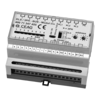
4.2 Setting the IP Address Mode
Though the Ethernet Module has two Ethernet Ports, it only has one
IP address that is used to target communications to the device. The
dip switch accessible on the top of the module is used to establish
the IP address Mode. The switch settings and the resulting behav-
iors are depicted in the table below.
Table 9. IP Address Switch Settings
Value Mode
Behavior at reset (power cycle or configura-
tion reset button)
0 Restore The operating IP configuration will be set to the
follow values:
IP Address = 192.168.1.254
Net Mask = 255.255.255.0
Gateway = 192.168.1.1
Note: This mode is intended for fast recovery
from an unknown static IP configuration. The switch
Value must be changed to apply a new IP setting
1-253 Static
(HW)
The Value determines the last byte of the IP
address. The rest of the IP configuration will be
equal to the Static NV values set via web pages or
other protocol.
Note: This mode is intended for applications where
fast deployment of devices without web configura-
tion is important.
254 Static
(NV)
The IP configuration will be set to the values stored
in NV memory. The default NV values from the fac-
tory are:
IP Address = 192.168.1.254
Net Mask = 255.255.255.0
Gateway = 192.168.1.1
These can be changed from the web page or by
writes to modbus registers.
255 DHCP The IP configuration is set by an external DHCP
server on the network.
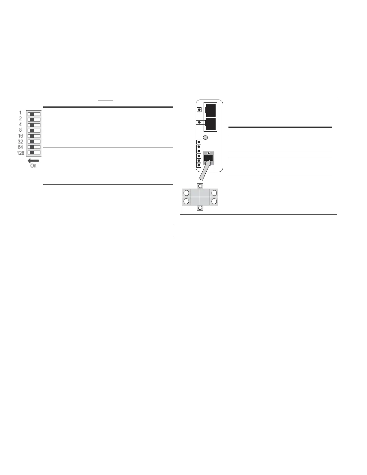
4.3 Connecting to the Modbus Serial Port
The serial port on the Ethernet module supports a Modbus RTU or
ASCII protocol as a slave device (default = RTU). The physical layer
settings for the device have the following default values, and can
be modified through the web page or writing to Modbus registers.
A 4-pin connector is provided to connect the device to the Modbus
network as shown in the figure below. Two of the pins provide an
additional connection point for the 24 Vdc power supply.
Setting Default Range
Address 1 1 to 247
Baud Rate
19.2K
9600, 19.2K,
57.6K, 115.2K
Stop Bits 1 1 or 2
Parity Even Even or Odd
Mode RTU RTU or ASCH
Figure 8. Serial Modbus Connection
ote:N When the C441U or C441V are used with the C440 overload relay, this
serial port is used to connect to the C440 serial port and is NOT available as a
serial monitoring port.
P1
P2
-
+
D1
D0
 Loading...