14
User Manual MN04200002E
Effective January 2016
C441 Ethernet module user manual
(C441R, C441T, C441U, C441V)
EATON www.eaton.com
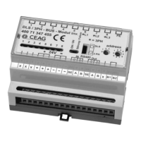
4.5 S811+ to C441U and C441V
Figure 12. S811+ to C441U and C411V Wiring Diagram
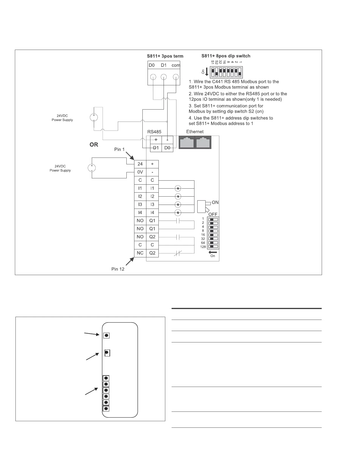
4.6 Status Indicators
The Ethernet module includes indicators for the module status (MS),
Network Status (NS), Input Status (I1-I4) and Output Status (O1-O2).
Figure 13. Status Indicators
I1
I2
I3
I4
O1
O2
MS
NS
Module Status
Network Status
I/O Status
The Module Status Indicator states are described in the table below
Table 10. Module Status Indicator
Indicator State Summary Requirement
Steady Off No Power If no power is supplied to the device, the module
status indicator shall be steady off.
Steady Green Device
Operational
If the device is operating correctly, the module sta-
tus indicator shall be steady green.
Flashing Green Standby If the device has not been configured, the module
status indicator shall be flashing green.
Flashing Red Minor Fault If the device has detected a recoverable minor fault,
the module status indicator shall be flashing red.
Note: An incorrect or inconsistent configuration
would be considered a minor fault. “This fault indi-
cation will be active when the target device (C441,
C440, S611) is not powered up or not connected
to the communication adapter. Check connections
and attempt a power cycle of the communication
adapter and target device.”
Steady Red Major Fault If the device has detected a non-recoverable major
fault, the module status indicator shall be steady
red. This fault can be generated by an NV memory
read failure. A factory reset should be attempted to
clear the issue.
Flashing Green/
Red
Self-test While the device is performing its power up testing,
the module status indicator shall be flashing green
/ red.
 Loading...