Matrix Telecom Inverter System
4
Copyright © 2008-2010 Eaton Corporation. All Rights Reserved.
IPN 997-00012-68D February 2010
Maintenance Bypass Switch (MBS) and Power Distribution Unit (PDU) (optional)
The 50A and 100A maintenance bypass switches allow for the safe removal of inverters or the
static transfer switch without load power interruptions.
For more information refer to STS/MBS Operation on page 59
.
The power distribution unit includes input circuit breakers, output circuit breakers (with 50A
MBS only) and terminals. The ac output can be connected to the rear screw terminals or to the
eight rear-mounted IEC connectors (with 50A MBS only).
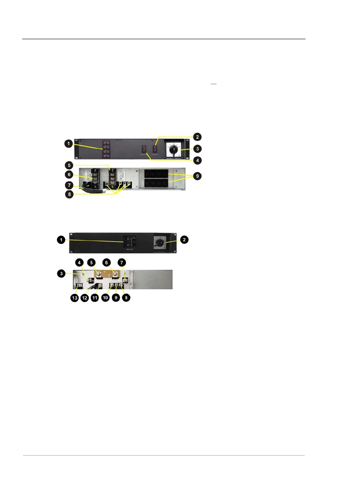
50A MBS and PDU (INV-MBSDU-50)
"
Output circuit breakers (for IEC
plugs on rear)
#
Input circuit breaker (100A)
$
Maintenance bypass selector
switch.
%
Output circuit breaker (100A)
!
AC output terminals
&
AC input terminals
3
Signal cable to STS shelf (CN1)
4
AC connectors to STS chassis.
5
AC output IEC connectors.
100A MBS (INV-MBS-100)
"
Input circuit breaker (125A)
#
Maintenance bypass selector
switch (125A)
$
Ground (GND)
%
AC input N
!
AC input L
&
AC output L
3
AC output N
4
AC-L - from STS shelf
5
Ground (GND) - from inverter shelf
'
AC-N - from inverter shelf
(
STS-L output
)
Signal cable to STS shelf (CN1)
*
AC-L input L to STS
 Loading...