Installation
Copyright © 2008-2010 Eaton Corporation. All Rights Reserved.
IPN 997-00012-68D February 2010
25
Step 4 - Connect AC Output Wires to STS (if required)
Ignore this Step if a maintenance bypass switch (MBS) is fitted.
If no maintenance bypass switch (MBS) is fitted:
• Refer to the Wire Size Tables on page 16
and local wiring rules, and select
the correct size ac cable.
• Terminate the cables with M4 crimp lugs.
• Connect ac input line to L-AC. Connect AC input neutral to AC-N.
• Connect ac output line to AC-L OUT. Connect AC output neutral to AC-N.
• Secure the connections with the screws and washers supplied. Tighten the
screws according to the Standard Torque Settings on page 58
.
Do not connect the other end of cables to the ac load equipment at this stage.
Procedure complete
Task 8 - Connect MBS (if used)
Step 1 - Remove MBS rear cover
Step 2 - Connect Signal Cable between MBS, STS and Inverter Chassis
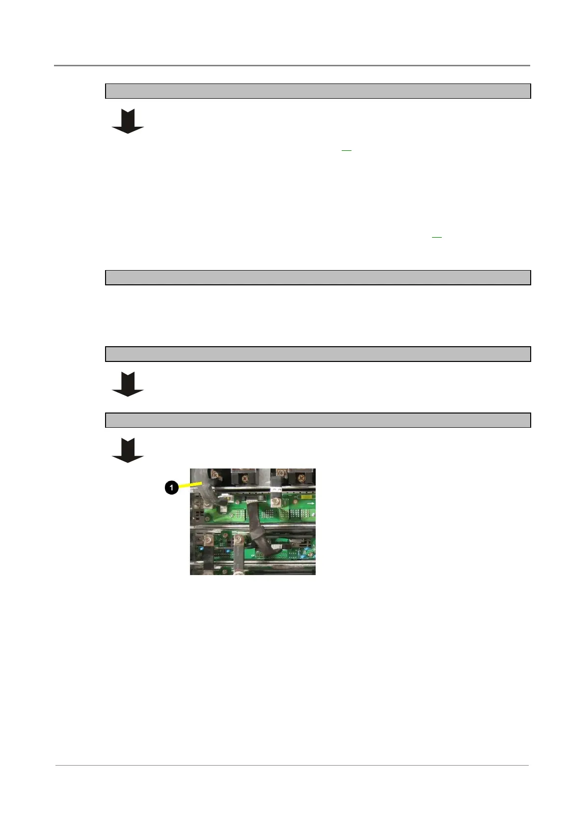
Connect the 4-pin MBS cable to connector CN1 on the controller/interface/STS
chassis. (If fitted, remove the 4-pin jumper from CN1.)
"
4-pin MBS cable to connector
CN1 on the
controller/interface/STS chassis
backplane.
 Loading...