Matrix Telecom Inverter System
26
Copyright © 2008-2010 Eaton Corporation. All Rights Reserved.
IPN 997-00012-68D February 2010
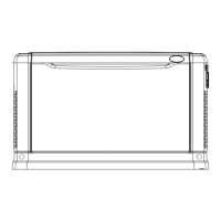
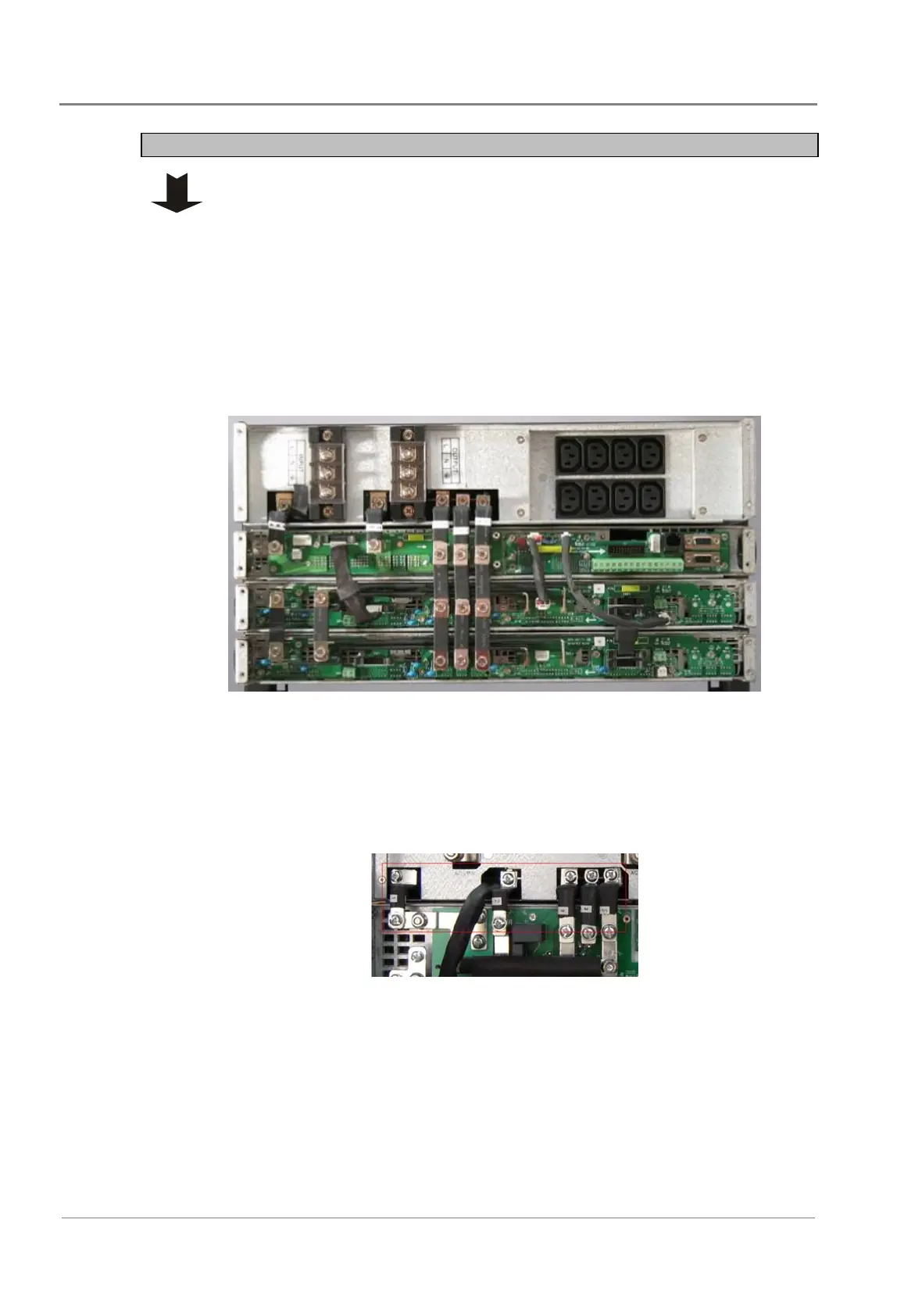
Step 3 - Connect AC Bus Bars
When necessary, use the spacers provided to keep the bars vertical.
Connect the 5 bus bars supplied with the MBS/PD shelf from UC3, UC2, UC1
on STS backplane PCB to the corresponding connectors on the MBS/PD shelf.
• 50A MBS:
• Bus Bar 1 for UC3 (inverter output N)
• Bus Bar 1 for UC2 (Ground)
• Bus Bar 2 x 1 for UC1 (inverter output L)
• Bus Bar 3 x 1 for UC4 (STS output L)
• Bus bar 4 x 1 for UC5 (AC input L)
• 100A MBS:
• Bus Bar 3 for inverter output N
• Bus Bar 3 for Ground
• Bus Bar 5 x 1 for inverter output L
• Bus Bar 2 x 1 for STS output L
• Bus bar 1 x 1 for AC input L
 Loading...