Installation
Copyright © 2008-2010 Eaton Corporation. All Rights Reserved.
IPN 997-00012-68D February 2010
27
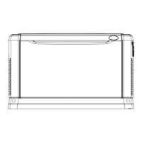
Step 4 - Connect AC Wires
1 Refer to the Wire Size Tables on page 16
and local wiring rules, and select
the correct size ac cable.
2 Terminate the cables with M4 crimp lugs.
3 Route the ac input cables to the AC input terminals on the back left of
MBS/PD shelf. Connect according to the labels.
4 Either:
• Connect AC output cables to the ac output terminals on the back right
of MBS shelf. Connect according to the labels, or
• For 50A MBS only, connect to the ac output IEC connectors.
50A MBS
100A MBS
Do not connect the other end of cables to the ac load equipment at this stage.
Procedure complete
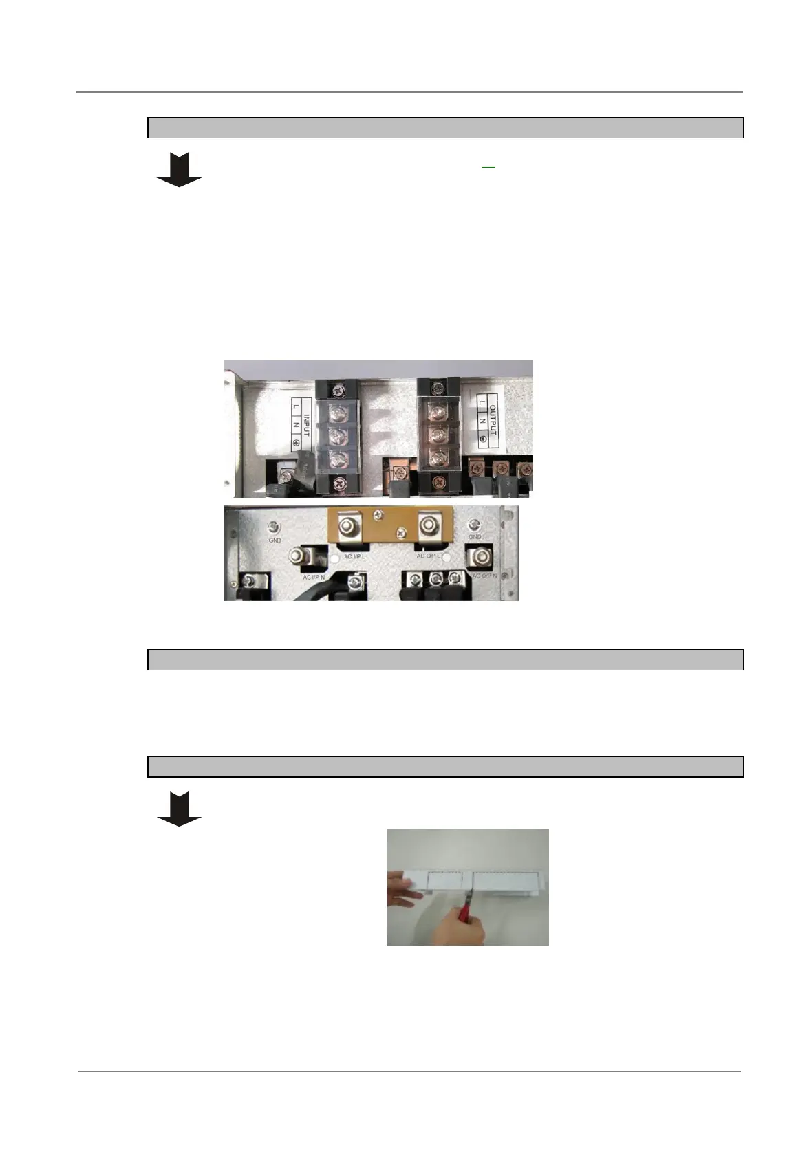
Task 9 - Rear Covers
Step 1 - Remove knockouts
On each rear cover, remove the knockouts necessary to fit around the bars and
cables.
 Loading...