Matrix Telecom Inverter System
14
Copyright © 2008-2010 Eaton Corporation. All Rights Reserved.
IPN 997-00012-68D February 2010
Task 2 - Controller/Interface/STS Chassis Assembly
Ignore this Task if the controller/interface/STS chassis is not fitted.
Step 1 - Change mounting brackets if required
The controller/interface/STS chassis is pre-installed with 19-inch rack
brackets.
For 23-inch rack mounting, replace the mounting brackets.
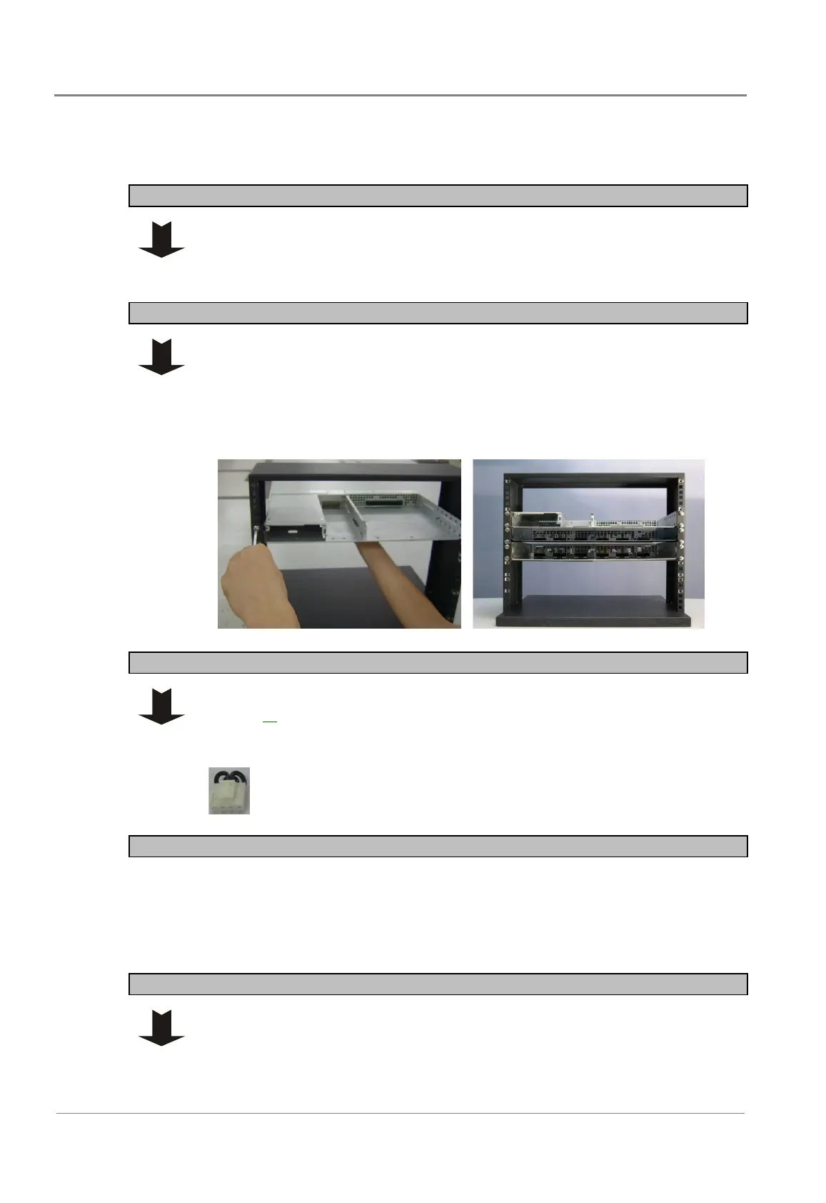
Step 2 - Mount chassis
Each controller module or interface module can control up to 12 inverter units
cascaded. It is recommended to install the controller/interface/STS chassis above
or below the inverter shelves to ease inter-connections.
1 Fit the controller/interface/STS chassis (either 50A or 100A) to the
equipment rack, and align holes of mounting brackets and rack.
2 Secure the chassis with the four screws provided.
Step 3 - Insert jumper in CN1 on STS backplane (if required)
Ignore this Step if a maintenance bypass switch (MBS) is to be fitted. See details
on page 25
.
If no maintenance bypass switch (MBS) is to be fitted, insert the 4-pin jumper
into connector CN1 on the STS backplane.
Procedure complete
Task 3 - Install MBS/PDU chassis
Ignore this Task if the MBS/PDU chassis is not fitted.
Step 1 - Change mounting brackets if required
The MBS/PDU chassis is pre-installed with 19-inch rack brackets.
For 23-inch rack mounting, replace the mounting brackets.
 Loading...