Installation
Copyright © 2008-2010 Eaton Corporation. All Rights Reserved.
IPN 997-00012-68D February 2010
13
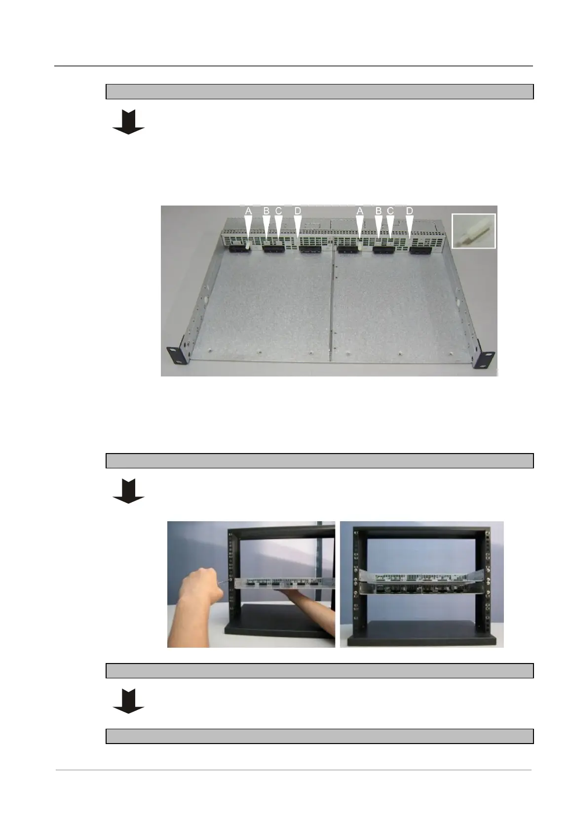
Step 2 - Fit nylon module identification spacers
WARNING: The system will fail to operate normally if inverter modules of
different specification are inserted inverter shelves. The supplied nylon spacers
(two per shelf) to ensure only inverter modules of the same specification can be
fitted.
Insert the supplied nylon spacer into the correct holes on the shelf, based on
module models as shown below.
There are four holes above the connectors in each inverter slot.
Position A for INV-4815
Position B for INV-4815E
Position C for INV-4810
Position D for INV-4810E
Step 3 - Mount chassis
1 Fit the inverter chassis to the equipment rack, and align holes of mounting
brackets and rack.
2 Secure the chassis with the four screws provided.
Step 4 - Repeat for other inverter chassis as required
Each inverter chassis holds two inverter modules. Repeat Steps 1 - 3 to install
the remaining inverter chassis.
Procedure complete
 Loading...