EasyManua.ls Logo

Eaton Matrix Telecom Inverter System User Manual

Eaton Matrix Telecom Inverter System
86 pages
To Next Page IconTo Next Page
To Previous Page IconTo Previous Page
Page #54 background image
Matrix Telecom Inverter System
48
Copyright © 2008-2010 Eaton Corporation. All Rights Reserved.
IPN 997-00012-68D February 2010
Alarm Code Tables
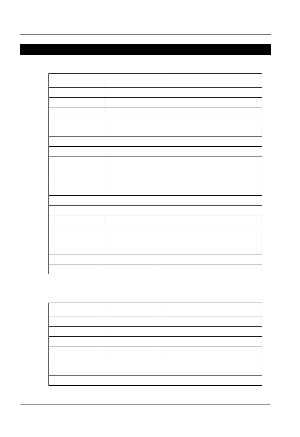
Inverter Alarm Codes
Alarm Name Level Remark
Inverter fault Major Inverter fault
Inv over load Observe Inverter Over-loading
Inv fan fault Major Inverter Fan fault
Inv power limit Major Inverter power limit
DC input Abnormal Major Inverter input abnormal
Inv low volt off Major Inverter shut down due to low input volt
Inv Bus High Critical Bus volt over the maximal level
Inv Bus Low Critical Bus volt under the minimal level
Inv BusSoft fail Critical Bus Soft Start Fail
Inv Output short Critical Inverter Output Short
Inv OPV Low Critical Inverter output volt low
Inv OPV High Critical Inverter output volt high
Inv Temp High Critical Inverter Temperature High
NegPow Protect Critical Inverter negative power protection
SynPulse fault Critical Sync Pulse Fault
Inv EPO Critical EPO
SoftStart fail Critical Inverter soft start fail
Eeprom fail Major Inverter EEPROM fault
Inv Temp High Critical Inverter temperature high
Controller Alarm Codes
Alarm Name Level Remark
Inv lost Critical Inverter lost
STS lost Critical STS lost
DC input low Critical Bat Volt Low
Cont temp high Critical Controller temperature High
Cont eeprom fail Major Controller EEPROM fault
DC input Over Critical Bat voltage high
CAN Bus Off Critical Controller CAN bus off

Table of Contents

Questions and Answers:

Eaton Matrix Telecom Inverter System Specifications

General IconGeneral
Battery Voltage48 VDC
Output Voltage120 VAC
Form FactorRackmount
Frequency60 Hz
Efficiency90%
Operating Temperature0°C to 40°C

Summary

Chapter 1 General Description

Matrix Inverter System

Describes the integrated AC power system, its modular design, and redundancy.

Modules

Details the Inverter Module and Controller Module, including features and components.

Chapter 2 Preparation

Battery Precautions

Details safety measures for handling, charging, and disposing of batteries.

Wiring Requirements

Specifies electrical connection requirements, including grounding and symbols.

Chapter 3 Installation

Frame Assembly

Covers the assembly of inverter, controller, STS, and MBS chassis.

Wiring Connection

Explains procedures for connecting DC input and AC output cables.

Module Installation and Removal

Describes how to install and remove STS and inverter modules.

Chapter 4 Operation

Pre-Operation Check

Lists essential checks before powering on the inverter, STS, and controller.

Apply Power

Details the steps for applying power to the system and initial checks.

Status Monitoring

Explains how to monitor system status via the controller's LCD screen.

Parameter Setting

Guides on setting system parameters, including password protection.

Chapter 5 Maintenance

Troubleshooting

Provides tables for diagnosing and resolving system issues.

Alarm Code Tables

Lists alarm codes for Inverter, Controller, and STS modules.

Appendix A Specifications

Appendix B STS/MBS Operation

Related product manuals