Parameters
M-Max Series Adjustable Frequency Drive MN04020003E—October 2013 www.eaton.com 95
PID Controller (P9)
The M-Max series frequency inverters are provided with a
PID controller that you activate with P9.1 = 1. The controller
can be deactivated via a digital input (P3.12).
PID control is superimposed on the frequency inverter
function. You should therefore set all of the frequency
inverter’s drive-related parameters, such as maximum output
frequency (motor speed), acceleration and deceleration
ramps (mechanical load, belts). Frequency inverter and motor
are process-integrated actuators. The output frequency to
the motor (which determines the speed) is specified as
manipulated variable from the PID controller.
When the PID controller is activated, the setpoints and actual
values become process variables and are normalized
automatically into percentages (%). For example, the
specified setpoint (0–100%) here is the same as a volume
flow (0–50 m
3
/h). The actual value here is the volume flow
(m
3
/h) from a suitable sensor, which is evaluated again as a
percentage (0–100%).
If this process data is to be displayed in the physical variable
(m
3
/h), you can set the conversion with parameter P9.19
(see “Display factor (P9.19)”).
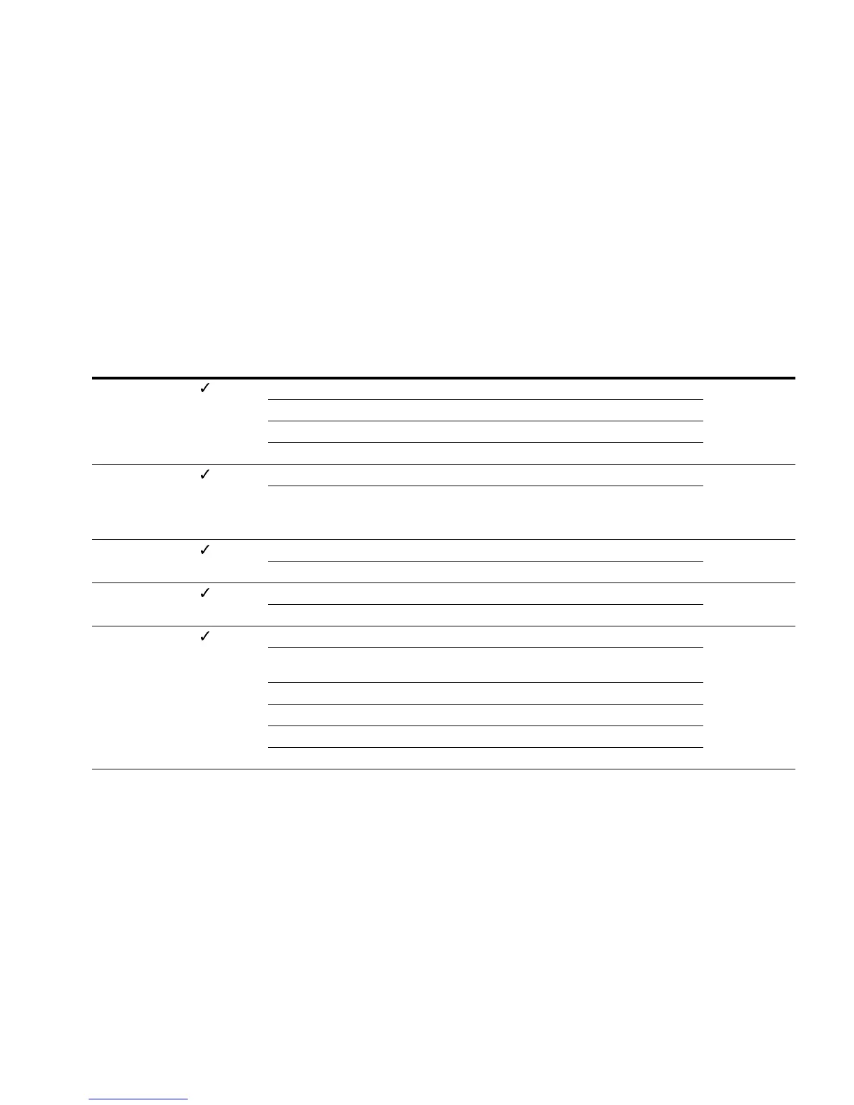
PID Controller
PNU ID
Access
RUN Value/Range Description
Factory Setting
(P1.3)
P9.1 163 — PID Controller 0
0 Deactivated
1 Activated for drive control
2 Activated for external application
P9.2 118 — PID controllers, P gain 100
0–1000% Proportional Gain (KP)
Low values attenuate the control action
High values can cause oscillation
P9.3 119 — PID controller, I reset time 10.0
0–320s Integral time constant
P9.4 167 — PID controller setpoint, keypad reference 0.0
0–100% Setpoint setting range utilizing keypad as reference P9.5 = 0
P9.5 332 — PID controller, setpoint source 0
— The setting range is limited by P6.3 (raised starting frequency)
and P6.4 (end frequency)
0 Keypad (P9.4)
1 Fieldbus
2 AI1
3 AI2
 Loading...