Installation
M-Max Series Adjustable Frequency Drive MN04020003E—October 2013 www.eaton.com 31
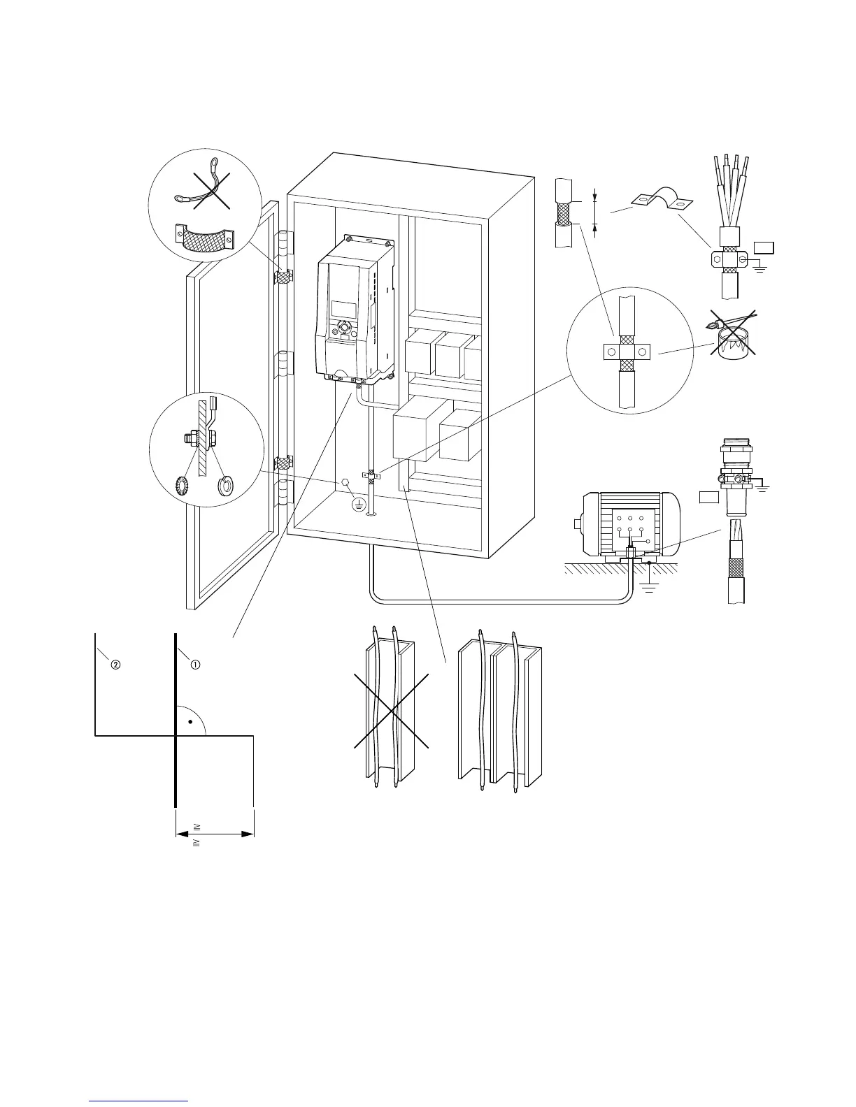
EMC-Compliant Setup (Example: M-Max)
Notes
Power cable: L1, L2/N, L3 and U/T1, V/T2, W/T3, R+, R–
Control and signal lines: 1 to 26, A, B, fieldbus connection
Large-area connection of all metallic control panel components.
Mounting surfaces of frequency inverter and cable shielding must be free from paint.
Connect the cable shielding in the output of the frequency inverter with a large surface area contact to the ground potential (PES).
Large-area cable shield contacts with motor.
Large-area earth connection of all metallic parts.
PE
PES
W2
U2
V2
U1
V1
W1
PE
11.81 in
115/120 Vac
230/240 Vac
400 Vac
460/480 Vac
575 Vac
24 Vdc
115/120 Vac
230/240 Vac
400 Vac
460/480 Vac
575 Vac
24 Vdc
( 300 mm)
PES
0.59 in
(15 mm)
å
åå
åååå
ååååå
åå å
ååå
 Loading...