Installation
M-Max Series Adjustable Frequency Drive MN04020003E—October 2013 www.eaton.com 29
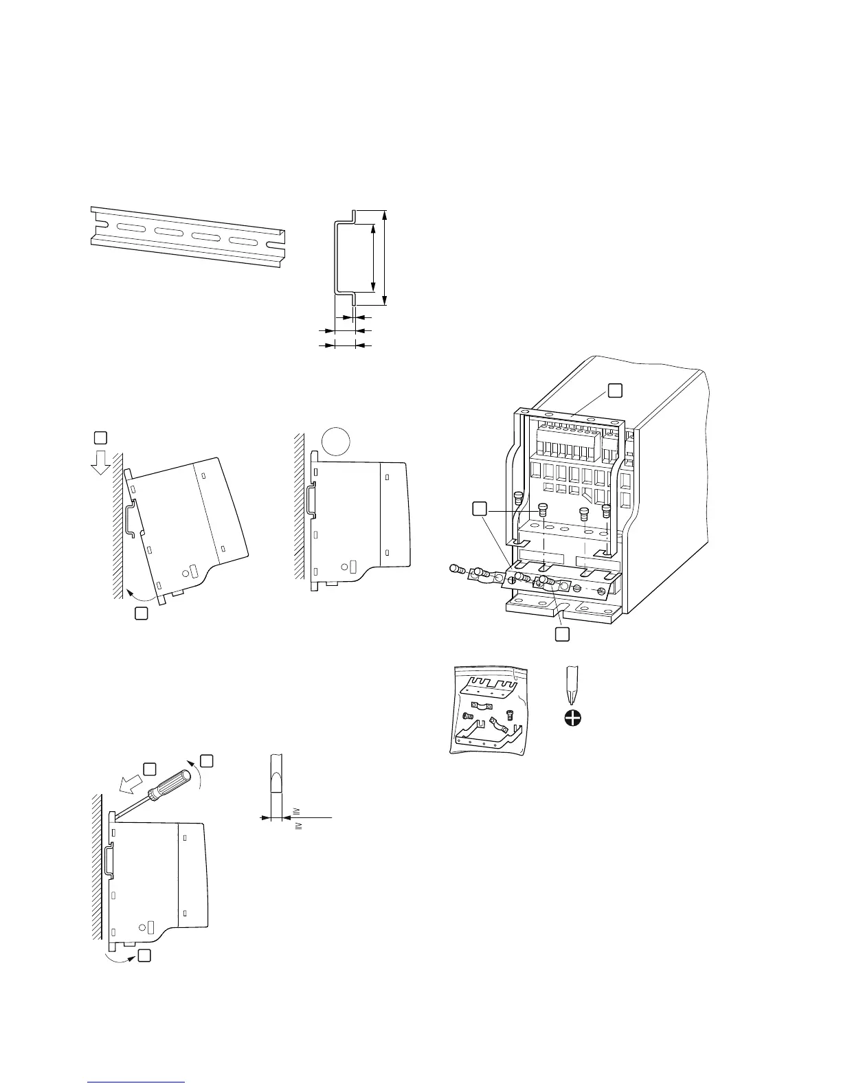
Fastening on Mounting Rails (FS1–FS3)
As an alternative, you can also fasten FS1–FS3 to a mounting
rail conforming with IEC/EN 60715.
Mounting Rail Conforming with IEC/EN 60715
Set the frequency inverter onto the mounting rail [1] from
above and press until it rests in place [2].
Fastening to the Mounting Rail
Dismantling from Mounting Rails
To remove the device, push the spring-loaded clip down. A
marked cutout is provided on the upper edge of the M-Max
device. A flat-bladed screwdriver (blade width 0.20 in [5 mm])
is recommended for pushing the clip down.
Demounting
Cable Flange Plate (Accessories)
The M-Max is supplied with a cable routing plate and
brackets. These enable you to arrange the connection cables
as required on the frequency inverter and fasten the shielded
cables in accordance with EMC requirements.
First, install the cable clamp plate for the connection lines in
the power section [1] and then the cable clamping plate [2]
for the control lines. The required installation screws (M4) are
included as standard.
[3] = gland plates in the power section.
Mount the cable routing plate before the electrical
installation.
Mounting the Cable Routing Plate and the Brackets
25
35
1
7.5
15
2
1
CLICK!
1
2
3
0.20 in
( 5 mm)
L1 L2/N L3
U/T1
V/T2
W/
T3
1
2
3
= M4
11.5 lb-in
(1.3 Nm)
 Loading...