Installation
42 M-Max Series Adjustable Frequency Drive MN04020003E—October 2013 www.eaton.com
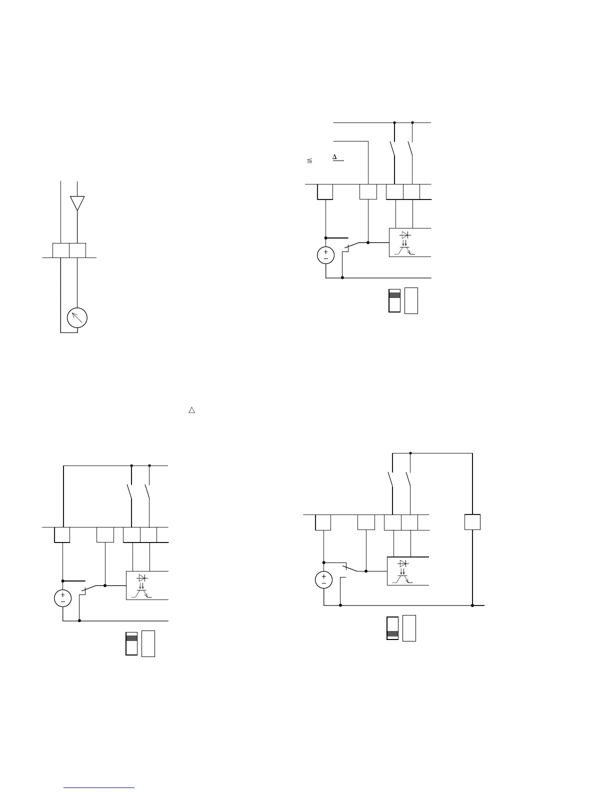
Analog Outputs
The frequency inverter provides an analog voltage signal
(0–10V) at control signal terminal 18. This signal is factory set
proportional to the output frequency (0–f
max
). The calibration
and parameterization of the analog output are described in
“Analog Outputs (P4)” on Page 77.
Analog Output AO (Connection Examples)
Digital Inputs
The frequency inverter has six digital inputs (DI1 to DI6) that
have an identical function and operation. Their actuation is
factory set for +24V (positive logic, source type). You can use
the device internal control voltage of control signal terminal 6
(+24V, maximal 50 mA) or an external voltage source (+24V)
with a residual ripple less than ±5% U
a
/U
a
. The
parameterizable functions are described in “Digital Inputs
(P3)” on Page 71.
Digital Inputs with Internal Supply Voltage
Digital Inputs with External Supply Voltage
The factory set functions and the electrical connection data
are shown in “Control Signal Terminal Functions” on
Page 40.
Microswitch S1 (LOGIC) is used to change the control logic
to so-called negative logic (sink type). The digital inputs are
connected internally or externally via control signal terminal 7
(DI_COM) directly to +24V and to the corresponding 0V
potential (GND) via input terminals DI1 to DI6.
Digital Inputs with Internal Supply Voltage
(Negative Logic, Sink Type)
5
0–10V
AO
18
GND
<10 mA
f-Out
–
+
789
DI1
DI2
DI_COM
S1
24V
6
<50 mA
+24V Out
S1 = LOGIC+
(Source Type)
LOGIC
– +
789
DI1
DI2
DI_COM
S1
6
<50 mA
+24V Out
S1 = LOGIC+
(Source Type)
LOGIC
– +
+ 24V
0V
(
±5%
)
U
U
a
a
789
DI1
DI2
DI_COM
S1
6
<50 mA
+24V Out
S1 = LOGIC–
(Sink Type)
LOGIC
– +
5
GND
 Loading...