Chengdu Ebyte Electronic Technology Co.,Ltd. 【8DO】MA01 -XXCX0080 User Manual
Copyright ©2012–2021,Chengdu Ebyte Electronic Technology Co.,Ltd.
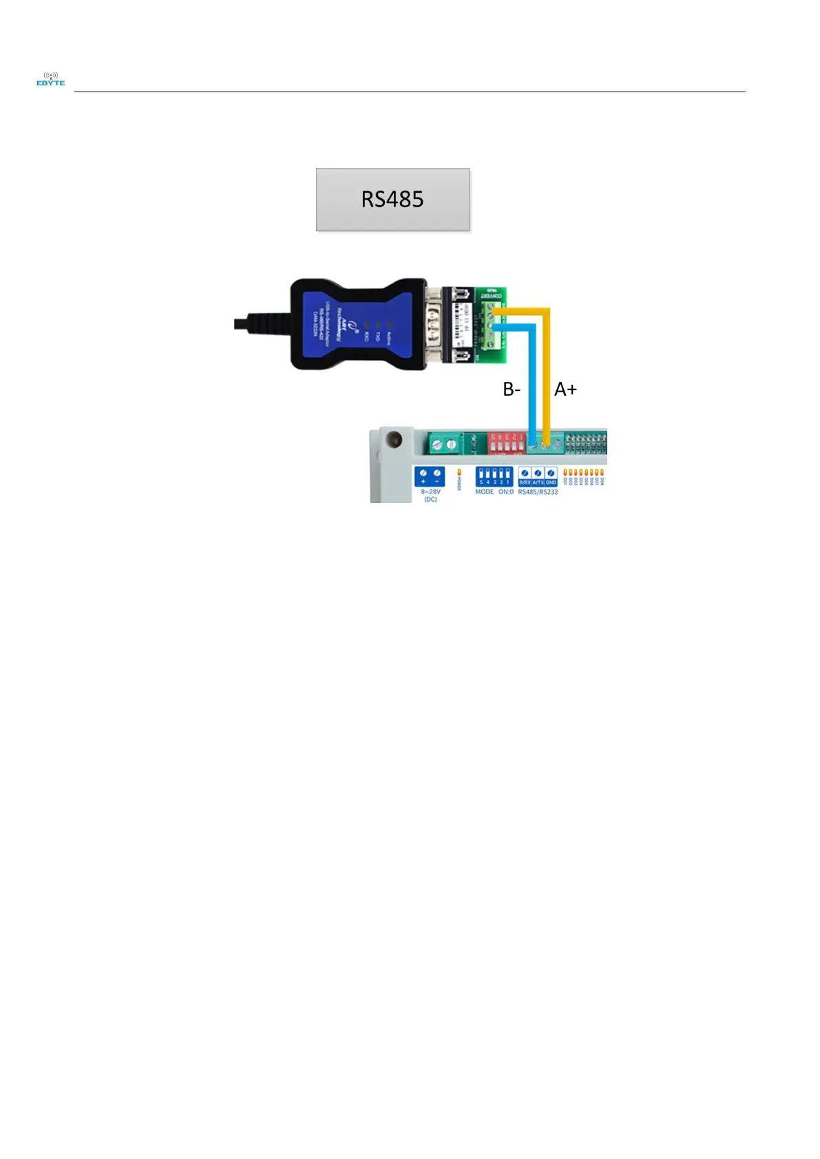
2.2.2 Communication Wiring RS485
Figure 2-2-2 Communication RS485 Wiring Diagram
2.2.3 Overall wiring diagram
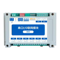
(1)After power is on on the device, the power LED(POWER)is on and the power supply to the device is ok.
(2)Analog input AI wiring, as shown by connecting the signal generator to the analog input AI port.
(3)Switch output DO wiring, as shown by connecting the load to the switch output DO port.
 Loading...