SOI/DT 2005-01 dmm 599 36 82-57
41/67
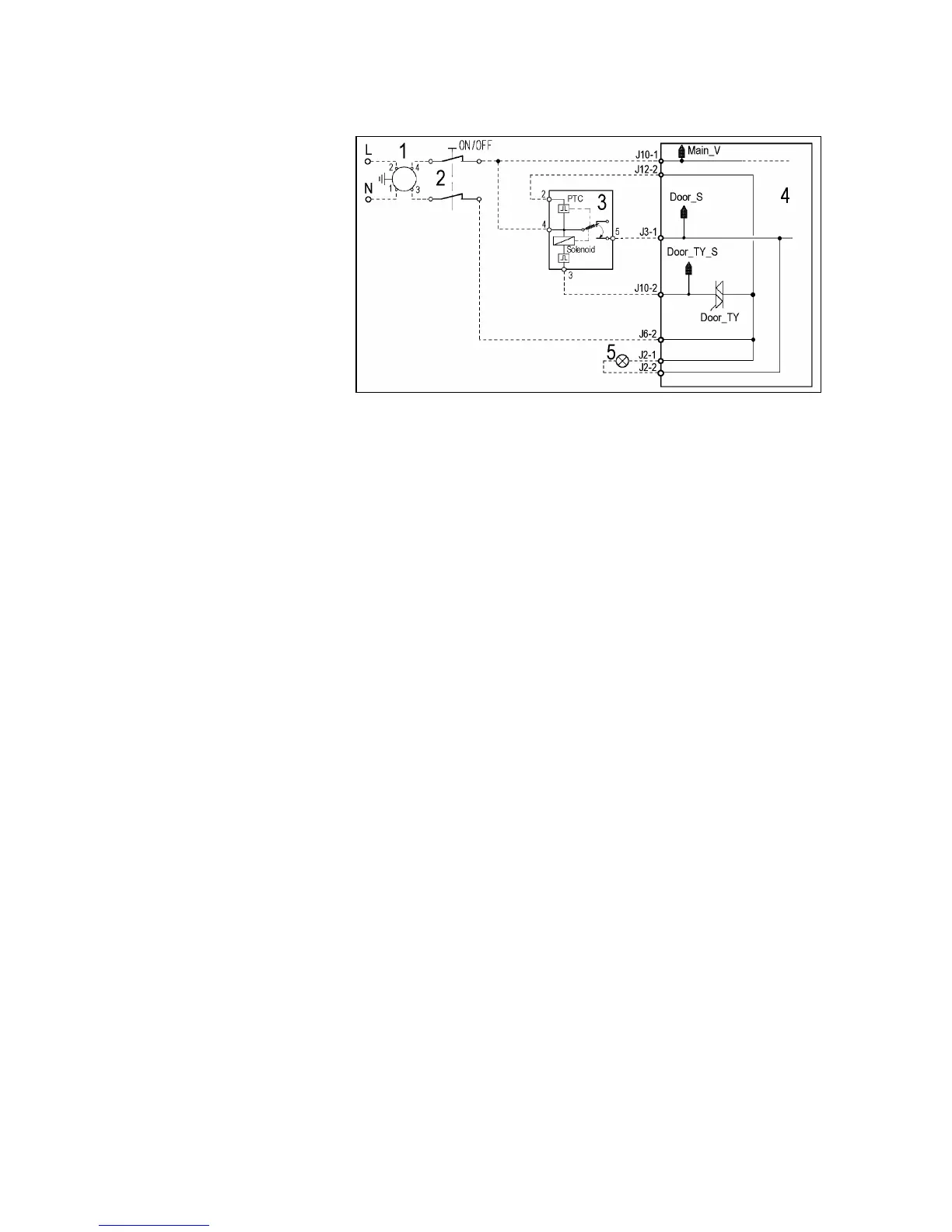
10.7.2 Instantaneous door interlock
1. Suppressor
2. Main switch (button or
programme selector)
3. Door interlock
4. Main PCB
5. Door pilot lamp off
• Operating principle
ª When the appliance is switched on, the ON/OFF switch closes and the bi-metal PTC (contact 4-2) is
powered; the door, however, is not locked.
ª When the programme starts (START/PAUSE button), the PCB transmits a 20 msec voltage signal to
contacts 4-3 of the solenoid valve (J10-2 connector of the board) (at least 6 seconds must elapse after
switching on); this signal locks the door and, at the same time, closes the main switch (contacts 4-5)
which powers all the components in the appliance.
• At the end of the programme, the PCB transmits two 20 msec signals (at an interval of 200 msec).
- the first signal does not release the door.
- the second signal (which is transmitted only if the system functions correctly) releases the door
interlock and at the same time the contacts of the main switch are opened.
• Conditions necessary for door release
ª Before transmitting the door release signals, the main PCB checks for the following conditions:
- the drum must be stationary (no signal from the tachometric generator)
- the water level must not be higher than the lower edge of the door
- the temperature of the water must not exceed 50°C.
• Automatic release device
ª In the event of a power failure, if the appliance is switched off, or if the solenoid should malfunction, the
bi-metal PTC cools over a period of 1 to 4 minutes, and then releases the door.
• “Door locked” pilot lamp
ª Certain models feature a pilot lamp which lights to indicate that the door is locked. This pilot lamp
switches off when the door can be opened.
 Loading...