FB2100/FB2200 Flow Computer CPU Enclosure & Electronics Field Replacement Guide
D301803X012
November 2020
9
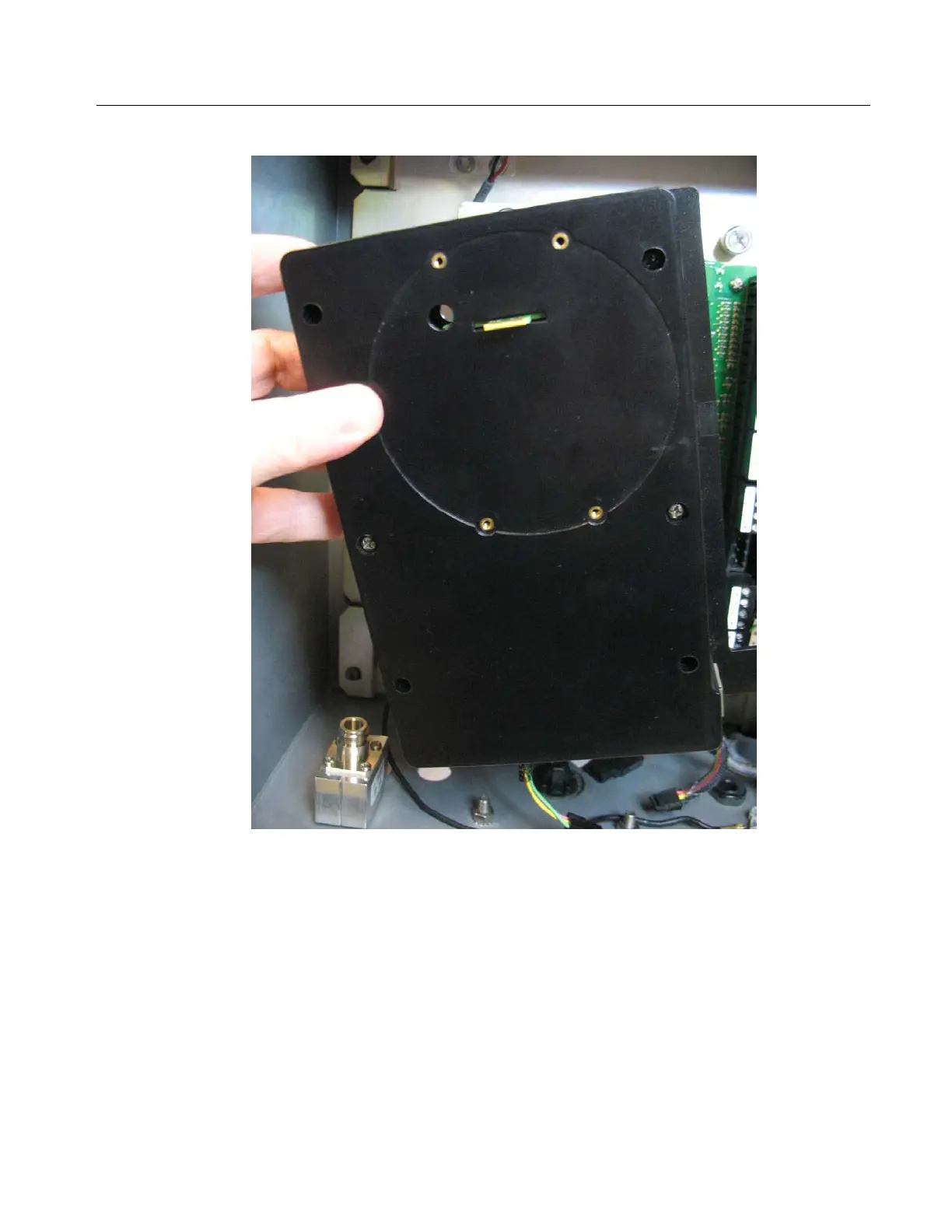
4.
Gently pull the CPU enclosure out of the flow computer enclosure.
Re-attaching the CPU Enclosure to the Battery Compartment
1.
Line up the CPU enclosure's captive fastening screws with their matching holes on the other
assemblies and battery compartment. Press the enclosure screws onto the holes and hold
the CPU enclosure while tightening each of the captive fastening screws with a torque of 7 to
9 in-lbs (0.8 to 1.0 N-m).
2.
Connect the cable between the CPU and the sensor module and make sure it has clearance.
3.
Replace the HMI module. See Replacing the HMI Module on page 6.
Removing/Replacing the CPU Enclosure Cover (Top)
UL Listed CPU Enclosure Cover (Top) Field Installed Accessory Kit for Use in Class I, Division 2,
Groups A, B, C, and D
 Loading...


