FB2100/FB2200 Flow Computer CPU Enclosure & Electronics Field Replacement Guide
D301803X012
November 2020
7
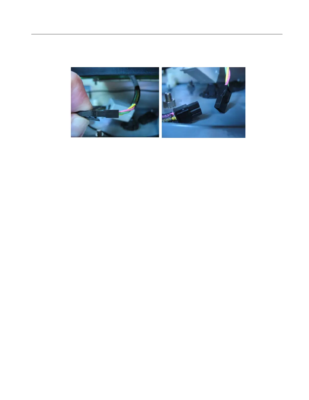
Disconnecting the Cable Between the CPU Enclosure and the Sensor
Disconnect the cable between the CPU enclosure and the sensor module. To do this, press down on
the outer edge of the connection tab, then pull the connectors apart.
Detaching/Re-Attaching the CPU Enclosure from/to the Battery Compartment
UL Listed CPU Box Field Installed Accessory Kit for Use in Class I, Division 2, Groups A, B, C, and D
Flow Computer CPU Box Option 1 Field Installed Accessory Kit Part No. 621673-01-0 for use
with UL Listed Model Series FB2100 and FB2200.
Flow Computer CPU Box Option 2 Field Installed Accessory Kit Part No. 621674-01-0 for use
with UL Listed Model Series FB2100 and FB2200.
Flow Computer CPU Box Option 3 Field Installed Accessory Kit Part No. 621675-01-0 for use
with UL Listed Model Series FB2100 and FB2200.
Flow Computer CPU Box Option 4 Field Installed Accessory Kit Part No. 621676-01-0 for use
with UL Listed Model Series FB2100 and FB2200.
This procedure applies if you are replacing an entire CPU enclosure with its electronics. In addition,
most field replacements of components inside the CPU enclosure require you to remove the CPU
enclosure from the flow computer enclosure.
Detaching the CPU Enclosure from the Battery Compartment
1.
Remove the HMI module. See Removing the HMI Module on page 6 for details.
2.
Disconnect the cable between the CPU enclosure and the sensor. See Disconnecting the Cable
Between the CPU Enclosure and the Sensor on page 7.
3.
Use a #2 Phillips-head screwdriver to loosen the four captive fastening screws that hold the
CPU enclosure to the battery compartment.
 Loading...


