EasyManuals Logo
Home>Emerson>Desktop>ControlWave Series

Emerson ControlWave Series Field Replacement Guide

Emerson ControlWave Series
26 pages
To Next Page IconTo Next Page
To Previous Page IconTo Previous Page
Page #5 background imageLoading...
Page #5 background image
FB2100/FB2200 Flow Computer CPU Enclosure & Electronics Field Replacement Guide
D301803X012
November 2020
3
Tip
Because some of these procedures involve removing small parts such as screws and standoffs, we
recommend you provide a container for holding small parts.
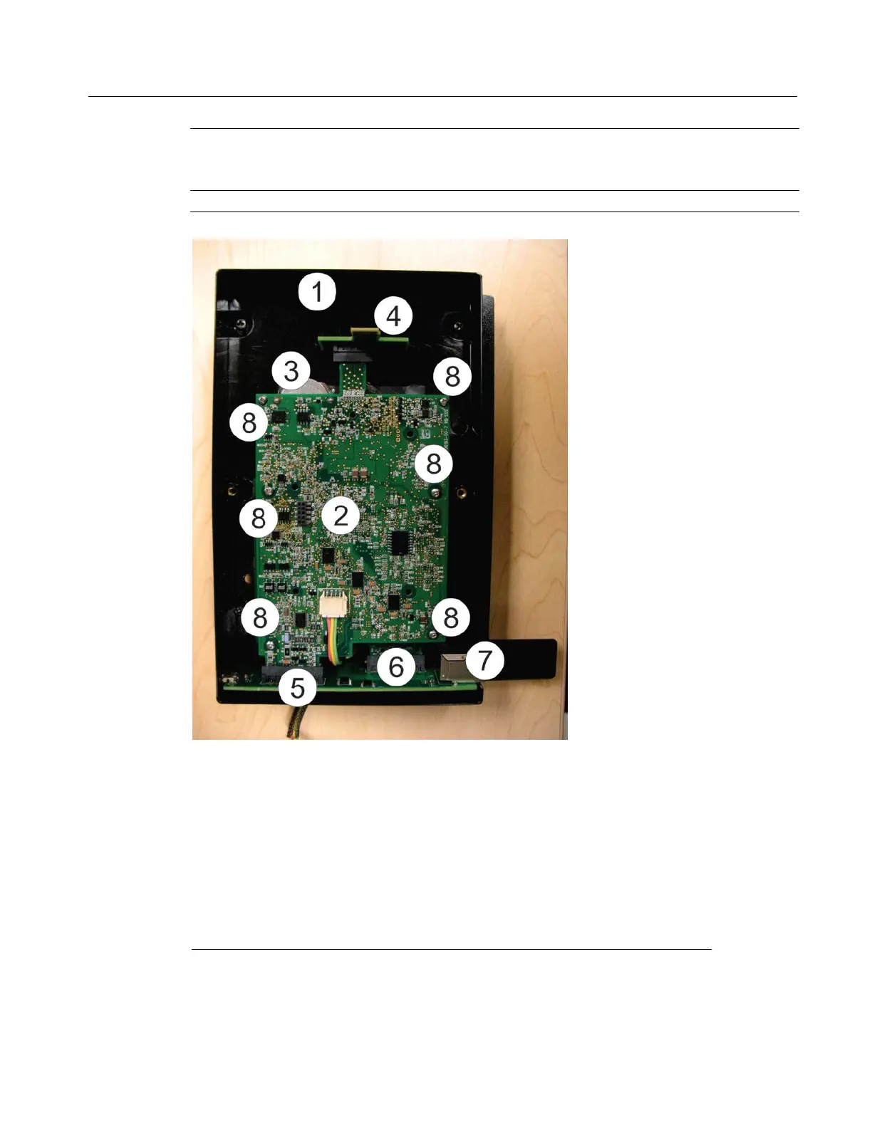
Components of CPU Enclosure
1
CPU enclosure (bottom)
2
CPU board
3
SRAM backup battery
4
Adapter board
5
Connectivity board
6
Connection for optional 6-Channel Expansion I/O Board (underneath
CPU) – (FB2200 only)
7
Ethernet port (active on FB2200 only)
8
Screws (6) if you have the 6-channel expansion I/O board installed
underneath, (4) if you do not.
Removing/Restoring Main Power
Except when replacing batteries or the HMI module, you must always remove main power when
performing field replacements.

Other manuals for Emerson ControlWave Series

Questions and Answers:

Question and Answer IconNeed help?

Do you have a question about the Emerson ControlWave Series and is the answer not in the manual?

Emerson ControlWave Series Specifications

General IconGeneral
BrandEmerson
ModelControlWave Series
CategoryDesktop
LanguageEnglish

Related product manuals