FB2100/FB2200 Flow Computer CPU Enclosure & Electronics Field Replacement Guide
D301803X012
November 2020
12
Removing/Replacing the Adapter Board
UL Listed Adapter Board Field Installed Accessory Kit for Use in Class I, Division 2, Groups A, B, C,
and D
Flow Computer Adapter Board Field Installed Accessory Kit Part No. 400209010-KIT for use
with UL Listed Model Series FB2100 and FB2200.
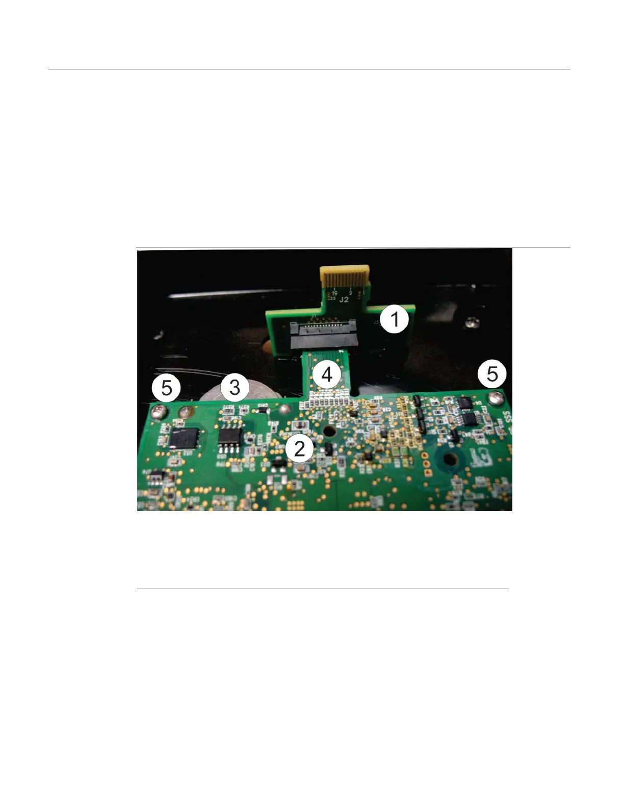
The adapter board resides inside the CPU enclosure. It provides a connection through a slot in the
CPU enclosure cover to the HMI module. You would remove/replace the adapter board if the
adapter board itself fails, or as a step in the field replacement of the CPU board, the 6-channel
expansion I/O board, the connectivity board, or the CPU enclosure (bottom).
CPU board connector to the adapter board
CPU screws nearest to the adapter board
Removing the Adapter Board
1.
Remove the HMI module. See Removing the HMI Module on page 6.
2.
Disconnect the cable between the CPU enclosure and the sensor. See Disconnecting the Cable
Between the CPU Enclosure and the Sensor on page 7.
3.
Detach the CPU enclosure from the battery compartment. See Detaching the CPU Enclosure
from the Battery Compartment on page 7.
4.
Remove the CPU enclosure cover. See Removing the CPU Enclosure Cover (Top) on page 10.
 Loading...


