FB2100/FB2200 Flow Computer CPU Enclosure & Electronics Field Replacement Guide
D301803X012
November 2020
2
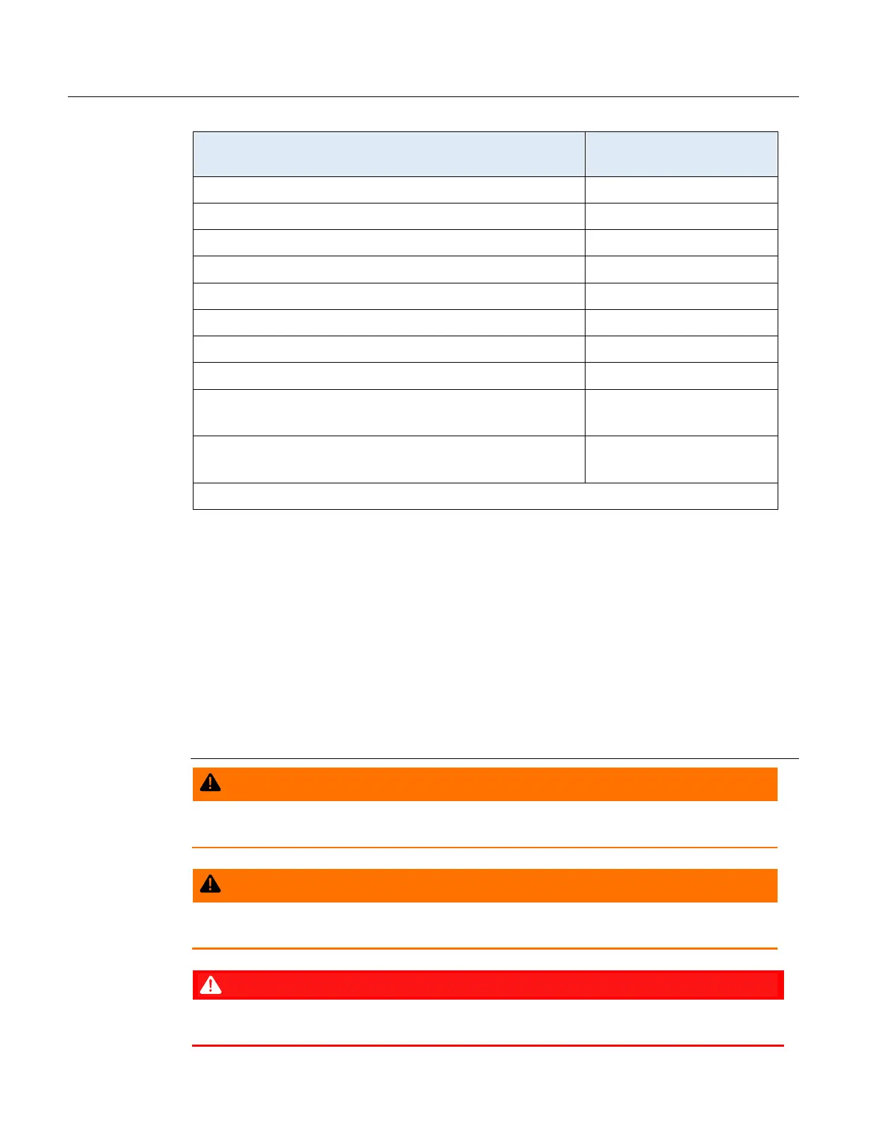
Refer to the table below for the correct field replacement part numbers.
Field Replacement Kit
Part Number
CPU Board 621678-01-0
Optional 6-Channel Expansion I/O Board 400215010-KIT
Connectivity Board 400211010-KIT
Adapter Board 400209010-KIT
CPU Enclosure - Bottom – (black plastic) 399260-01-0
CPU Enclosure – Top- (black plastic) 399264-01-0
CPU Enclosure Assembly with Base I/O - Ethernet disabled 621673-01-0
CPU Enclosure Assembly with Base I/O - Ethernet enabled 621674-01-0
CPU Enclosure Assembly with optional 6-Channel Expansion
I/O board – Ethernet disabled
621675-01-0
CPU Enclosure Assembly with optional 6-Channel Expansion
I/O board - Ethernet enabled
621676-01-0
UL File Number for these kits: E192567
Required Tools
#1 Phillips-head screwdriver
#2 Phillips-head screwdriver
Hexagonal torque wrenches. Ranges must include 1 to 2 in-lbs (0.1 to 0.2 N-m), 4 to 6 in-lbs
(0.5 to 0.7 N-m), 5 to 7 in-lbs (0.6 to 0.8 N-m), and 7 to 9 in-lbs (0.8 to 1.0 N-m).
Electrical Ratings:
Input Voltage: 10.5 Vdc to 30 Vdc external supply (Max power at 10 watts)
Ambient Temperature Range:
May be used up to a maximum ambient temperature of 80°C and a minimum ambient
temperature of –40°C; refer to the data plate attached to the device for ambient temperature.
EXPLOSION HAZARD – Substitution of any components may impair suitability for Class 1,
Division 2.
EXPLOSION HAZARD – Do not disconnect equipment unless power has been removed or the
area is known to be non-hazardous.
EXPLOSION HAZARD: Ensure the area in which you perform this operation is non-hazardous.
Performing this operation in a hazardous area could result in an explosion.
 Loading...


