FB2100/FB2200 Flow Computer CPU Enclosure & Electronics Field Replacement Guide
D301803X012
November 2020
19
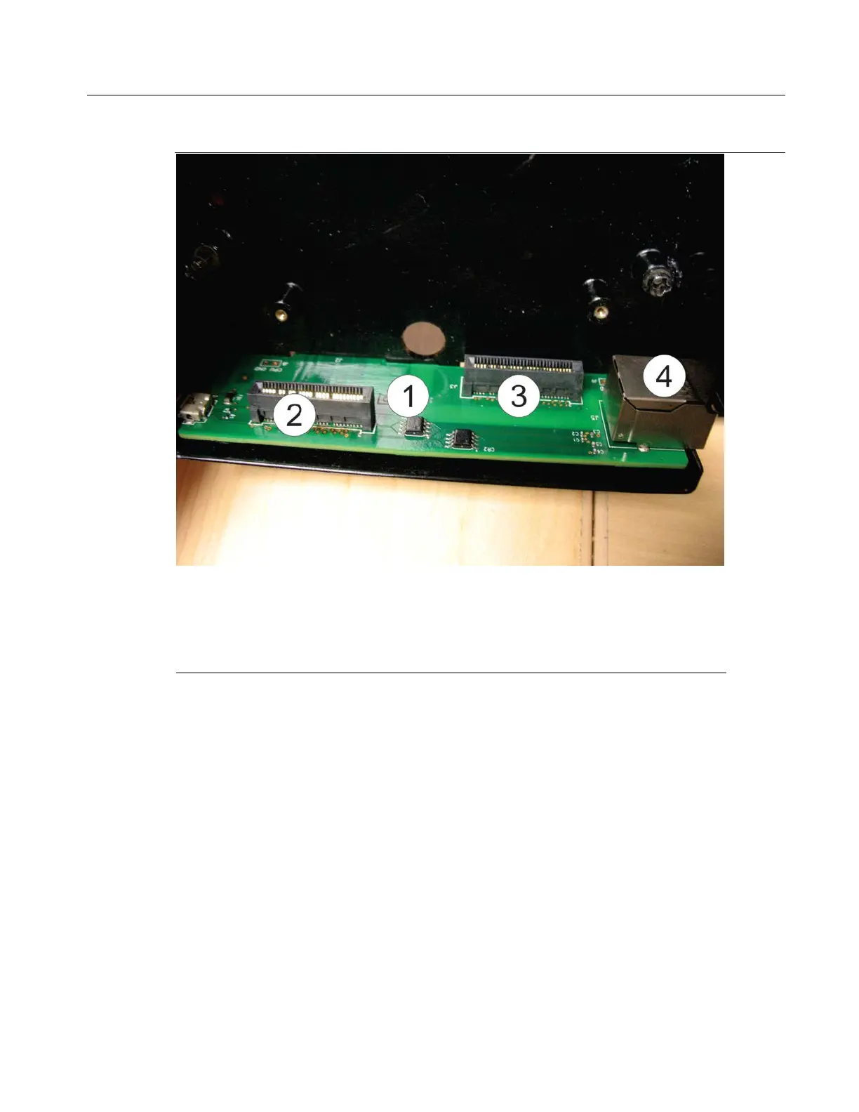
The connectivity board provides connections to the CPU board as well as the optional 6-channel
expansion I/O board inside the CPU enclosure.
Connectivity Board connector to the CPU board
Connectivity board connector to the optional 6-channel expansion I/O
board.
Ethernet port (active on FB2200 only)
The connectivity board sits on the side of the CPU enclosure. It has two connectors that go through
the bottom of the CPU enclosure to mate with the termination I/O board, and an Ethernet port
(active on FB2200 only), that goes through the side of the CPU enclosure.
 Loading...


