1592040000 XR70T EN v1.1 2019.07.09 XR70T 34/40
14. ALARM SIGNALLING
Compressor output according to Con e CoF
Depends on the relative function
Depends on the relative function
Depends on the relative function
Second high temperature alarm
Second low temperature alarm
Compressor and fan follows par. odC
14.1 ALARM RECOVERY
Probe alarms P1, P2, P3 and P4 are activated some seconds after detecting a fault condition in the relative
probe. These alarms are automatically reset some seconds after the relative probe restarts normal operations.
Always check the connections (probe – device terminals) before replacing the probe. Temperature alarms HA,
LA, H2 and L2 are automatically reset as soon as the temperature is within the normal working range. It is
possible to reset the “EE” alarm by pressing any button.
The alarms EA, CA and dA are automatically reset as soon as the relative digital input is disabled.
The internal buzzer can be muted by touching any area of the display and only if parameter tbA=Y.
15. SERIAL COMMUNICATION
The device supports different baudrates (par. bAU) and parity control (par. PAr).
Please check the serial network to adapt them according to the other devices.
The XJ485CX serial interface is required to convert the TTL output into an
RS485 signal.
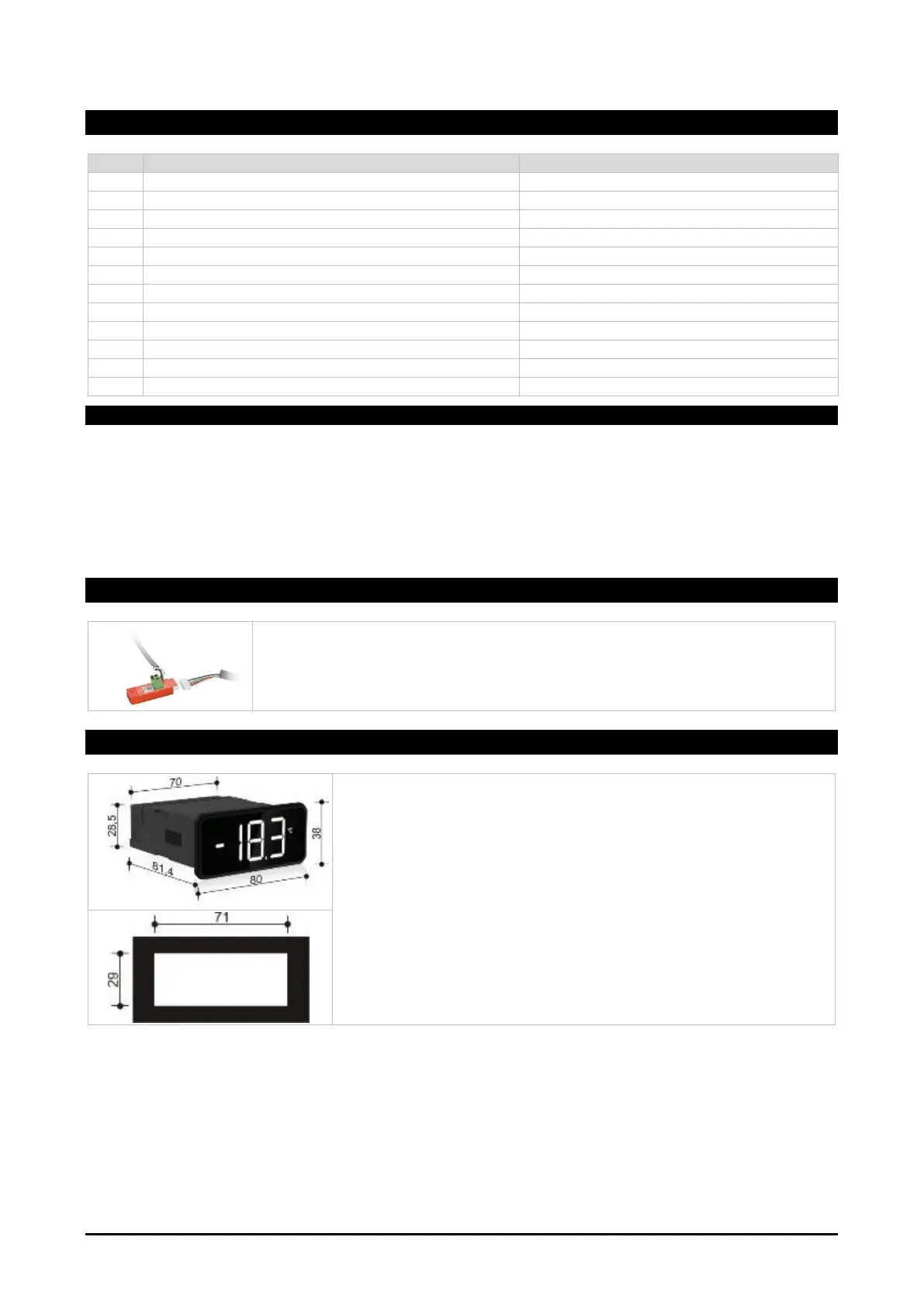
16. INSTALLATION AND MOUNTING
Instrument XR70T shall be mounted on vertical panel, in a 29x71 mm
hole, and fixed using the special bracket supplied. The temperature
range allowed for correct operation is 0 to 60°C. Avoid places
subject to strong vibrations, corrosive gases, excessive dirt or
humidity. The same recommendations apply to probes. Let air
circulate through the cooling holes.

 Loading...