3.4.1 Earth leakage protection
In all inverter devices like the EV3 drive, earth leakage current (DC, AC) may occur. To protect
against both kinds of leakage currents, an AC/DC-sensitive residual current circuit breaker must be
installed in front of the EV3 drive.
3.4.2 Grid supply and compressor wiring
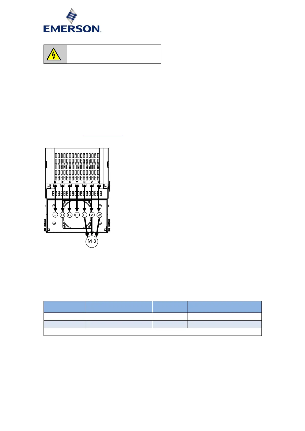
Figure 4 shows the general wiring to the power grid and to the compressor. This wiring diagram
does not show any system-related components like fuse breaker, RCD and the additional ferrites for
EMC.
Paragraph 3.4.6 "Control terminal" shows how to wire control-related components like DLT-sensor,
high-pressure limiter and the RS485 serial communication (Modbus) to the drive.
Figure 4: Wiring EV3150B, EV3185B
3.4.3 DC chokes
The integrated DC choke has protection class IP00 and temperature class H. The choke is positioned
between the heatsink of the drive and the drilled metal sheet, within the lower metal case. The fan
provides the necessary airstream for proper cooling. The chokes are fully covered to protect against
direct touching. Short connecting cables are used to minimize the possibility of EMI issues. The
choke dimensions are shown in Appendix 2: "Choke dimensions".
Table 8: DC chokes
3.4.4 Power grid connection
Table 9 includes information on how to connect the drive to the grid. The maximum input current is
based on a power factor of approximately 0.9. The ferrites, fuses and cable cross sections should be
considered as a recommendation and can be different based on the system design. One ferrite is
needed for the input cable (L1, L2, L3). The PE cable must not be passed through the ferrite. The
connection between the cables and the drive screw terminals should be done with 5 mm ring
terminals. The drives are IP20 protection class; therefore, make sure to re-screw the terminal
protection after wiring the drive in order to maintain the standard. Also, the use of isolated ring and
isolated blade terminals is mandatory for all terminals to maintain the IP20 class.
 Loading...


