16 AGL_Sol_EV3_E_Rev_02
5 Optional analog board
The analog board is foreseen for users who do not have the possibility to control the EV3 drive via
an RS485 communication and the Modbus protocol. To control the EV3 drive the analog board needs
a digital-enable signal and an analog signal to set the speed or heating demand. The drive
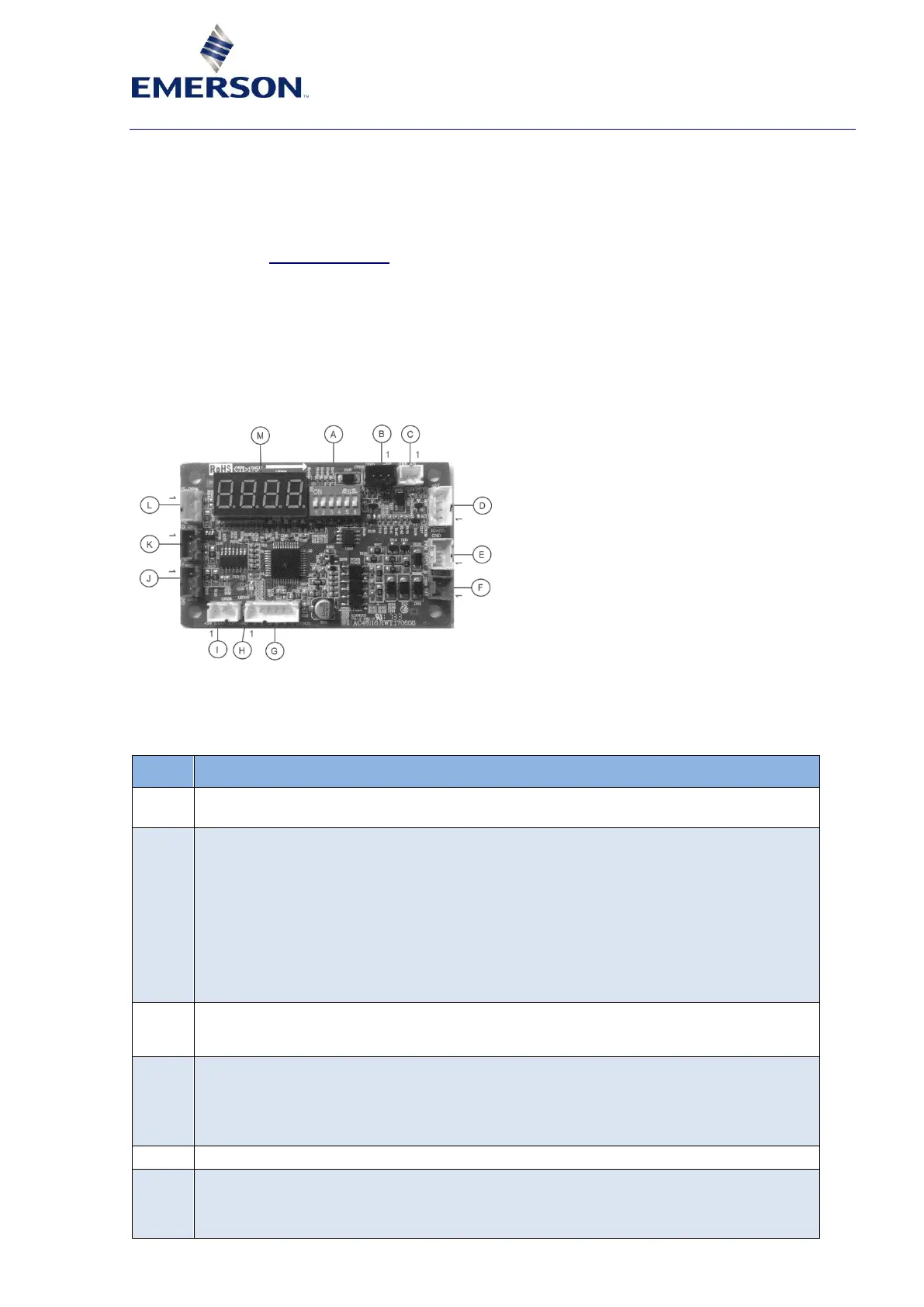
compressor package must be selected by a 6-digit DIP-switch. The 7-segment display shows the
status, failure codes as well the software version. The board also provides the system controller with
a PWM feedback signal with the main information. To protect the compressor a DLT sensor as shown
in paragraph 3.4.6 "Control terminal" must be wired to the drive control terminal.
If a DLT protection is already part of the system controller a wired resistance of 10 kΩ can bypass
this protection on the drive side. In normal operation it is possible to select limited or full speed range
via terminal L (CN104). Using the full speed range, the main controller must take care that in each
sub-envelope the speed does not go below the allowed speed. Using the limited speed range, the
compressor lowest speed is the one which is valid for the whole envelope and is called MMS
(Maximum Minimum Speed). In this case running at high load the compressor is well protected
against too low and too high speeds. In the Speed-Drop-Protection mode, the drive will only use the
limited speed range.
Figure 9: Analog control board
5.1 Terminal and LED description
Table 13 describes in detail the terminals shown in Figure 9 which are supported by the EV3 drive.
PWM-output feedback-signal:
▪ Pin 1: 5 VDC > NA
▪ Pin 2: PWM signal > Ext. controller digital input
▪ Pin 3: GND > Ext. controller GND
▪ Duty cycle (%):
0: Error (general error, miswiring)
25: Wrong compressor code (power cycle needed)
50: Standby (waiting for enable and 0…10 V signal)
75: SDP mode (Speed-Drop-Protection mode)
100: Running or heating mode
RS485 communication / power supply:
▪ Pin 1: RS485- (B) > EV3 drive control terminal: 5
▪ Pin 2: RS485+ (A) > EV3 drive control terminal: 4
▪ Pin 3: GND > EV3 drive control terminal: 3
▪ Pin 4: 5 VDC > EV3 drive control terminal: 2
Enable signal:
▪ Pin 1: (12 VDC or 24 VDC/AC)
▪ 12 VDC / 24 VDC/AC > Ext. controller enable signal
▪ Pin 2: GND > Ext. controller GND
 Loading...


