18 AGL_Sol_EV3_E_Rev_02
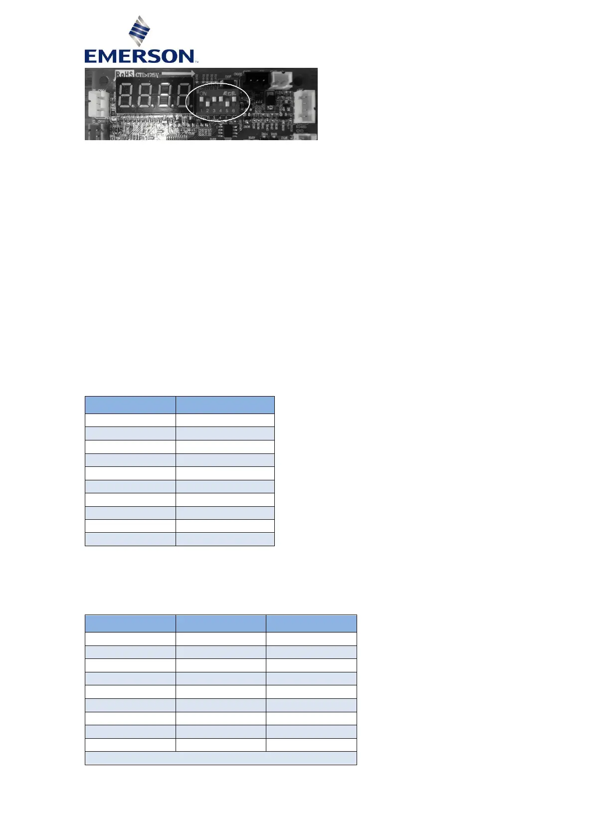
Figure 10: Analog control board code selection
NOTE: The binary code represents the binary transformation of the package code starting
from right to left (from 6 to 1).
5.2.2 Clearing faults
Faults are cleared automatically as long as the cause of the fault is no longer existing. In case of a
drive fault the analog board will automatically send the clear fault command to the drive. Once the
fault on the drive is gone the fault gets reset: after a delay time of approximately 30 seconds the drive
will return to normal operation mode.
5.2.3 Control signals
To control the compressor the analog board needs an enable signal between 12 and 24 VDC at
terminal F.
To control the speed and the stator heating demand a 0…10 VDC signal is required at terminal C.
A PWM feedback signal is available at terminal B.
5.2.4 Stator heating control
To control the stator heating of the compressor, the analog control board considers the range
between 1 and 1.9 V – see Table 15. The actual heating power depends on the type of compressor.
Table 15: Analog stator heating control mode
5.2.5 Speed control
To control the compressor speed, the analog control board considers the range between 2 and 9 V
of the analog input signal as the setpoint – see Table 16.
 Loading...


