Installation
December 2009
2-27
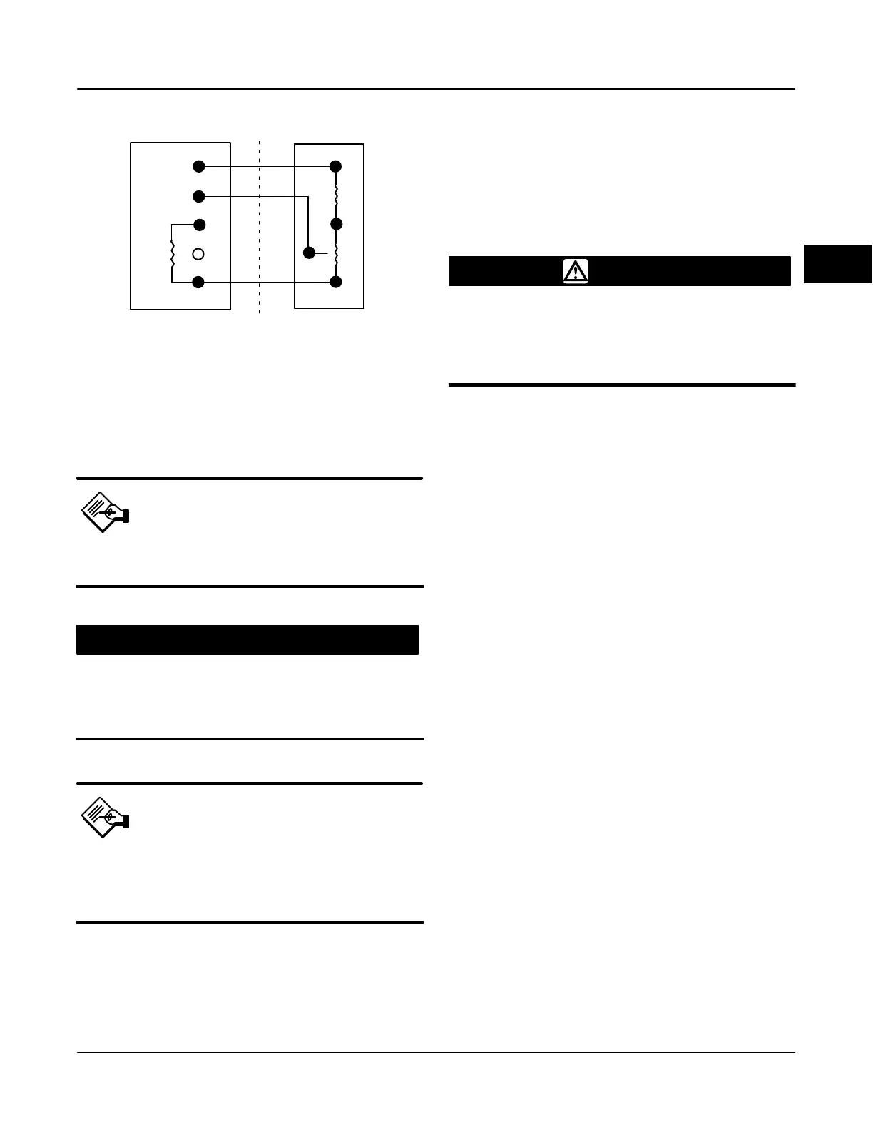
Figure 2-23. Terminal Details for Connecting a FIELDVUE
DVC6005f Base Unit and a Three-Resistor Series
3
1
30kW
(R
2
)
(R1)
2
(R
pot
)
BASE UNIT TERMINATION BOX
(DVC6005f)
THREE-RESISTOR SERIES
Note
The potentiometer must be capable of
resistance close to 0 Ohms.
CAUTION
To prevent damage to the
potentiometer, ensure that it is free to
travel the entire length of the actuators
travel.
Note
The digital valve controller must be
configured using the SStem/Roller
selection on the menu of the
appropriate setup device.
This procedure uses three resistors connected in
series; two fixed resistors and one potentiometer.
Three conditions must be met for the resistor
combination to correctly operate the digital valve
controller (refer to figure 2-23):
The maximum resistance of the potentiometer
(R
pot(max)
) must be between 3.9 kOhm and 10 kOhm.
The resistance of R
1
is 4.25 times greater than
R
pot(max)
.
The resistance of R
2
is 4 times less than
R
pot(max)
.
WARNING
To avoid personal injury or property
damage from an uncontrolled process
ensure that the R1 resistor is properly
insulated before installing it in the
terminal box.
1. On the base unit, remove the feedback
connections terminal box cap (see figure 2-16).
2. If necessary, install conduit between the base unit
and the remote travel sensor following applicable local
and national electrical codes. Route the 3-conductor
shielded cable between the two units (refer to figure
2-23).
3. Install the fixed resistor (R1) across the unlabeled
bottom Terminal and Terminal #1. The bottom terminal
does not have a screw. The screw on the 30 kOhm
terminal can be used. R1 must be properly insulated
when installed in the terminal box to prevent personal
injury or property damage.
4. Connect one wire of the 3-conductor shielded cable
between the unlabeled bottom Terminal on the base
unit and an end-lead on the external potentiometer
(Rpot).
5. Connect the second wire of the 3-conductor
shielded cable between the middle lead (wiper) of the
external potentiometer (R
pot
) and Terminal #2 on the
base unit.
6. Connect the third wire of the 3-conductor shielded
cable between a lead on fixed resistor (R
2
) and
Terminal #3 of the base unit.
7. Connect the available end-lead on the
potentiometer (R
pot
) with the available lead on fixed
resistor (R
2
).
8. Connect the cable shield or drain wire to the
ground screw in the feedback connections terminal
box of the base unit. Do not connect the shield or
drain wire to any lead on the three-resistor series.
9. Replace and tighten the base unit cover.
Example: Using a linear potentiometer rated at 400
Ohms/inch on an actuator with 16” of travel.
R
pot(max)
is 400 Ohms/in x 16” = 6.4 kOhm
2

 Loading...


