3 Wiring the channels
3.1 Available channels
Signal Channel A Channel B Channel C
Wiring
terminals
1 2 3 4 5 6
mA Inputs
and Outputs
mA Output 1 (HART) mA Output 2 RS-485
Frequency
Outputs
Frequency Output 2 Frequency Output 1
Discrete
Outputs
Discrete Output 2 Discrete Output 1
Discrete
Inputs
Discrete Input 1
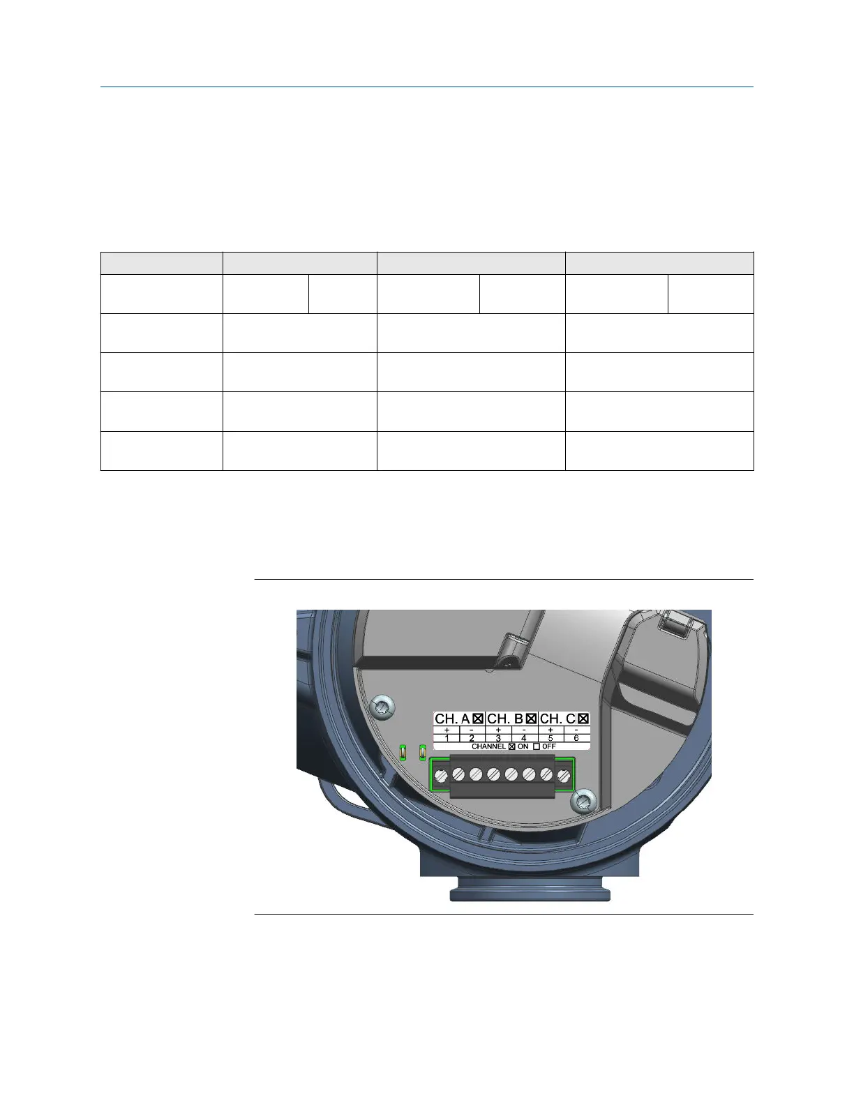
3.2 Access the wiring channels
Procedure
1. Remove the wiring access cover to reveal the I/O wiring terminal block connectors.
Figure 3-1: Channels on the Transmitter Terminal
2. Confirm which transmitter channels are activated, or ON, and identify the type of
configuration you will be wiring to based on the options available.
Installation Manual Wiring the channels
00825-0100-5710 October2023
Installation Manual 23
 Loading...


