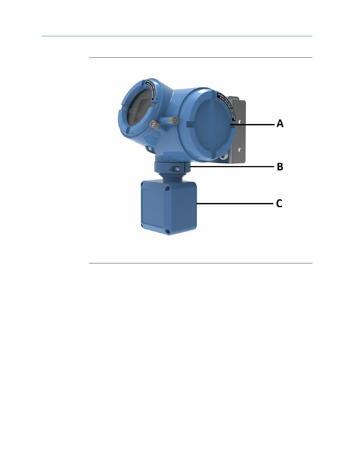
Figure 1-3: 4700 transmitter painted aluminum -- Remote mount
A. Transmitter housing cover
B. Clamping ring
C.
Junction box
The transmitter is installed remotely from the sensor. Both the 4-wire and the 9-wire
connection between the sensor and transmitter must be field wired.
For both integral mount and remote mount:
• The power supply and I/O must be field wired to the transmitter
• The I/O connections consist of three licensable channels (refer to Available channels).
1.5 Installation checklist
□ Safety messages are provided throughout this content to protect personnel and
equipment. Read each safety message carefully before proceeding to the next step.
□ When choosing a location for components, refer to the following guidelines:
— See the sensor installation manual for information on locating the sensor with
remote-mount or extended-mount electronics.
— Do not install a component in a location where its temperature, humidity, or
vibration limits will be exceeded.
— Maximum distance between components depends on the wire size, the wire type,
and the power supply. Ensure that sufficient power is supplied to the transmitter
terminals.
Installation Manual Planning
00825-0100-5710 October2023
Installation Manual 7
 Loading...


