□ Mount the meter in a location and orientation that satisfies the following conditions:
— Allows sufficient clearance to open the transmitter housing cover. Install with 8–10
inches (200–250 mm) clearance at the wiring access points.
— Provides clear access for installing cabling to the transmitter.
— Provides clear access to all wiring terminals for troubleshooting.
1.6 Power requirements
Universal (self-switching) AC/DC input, automatically recognizes supply voltage:
• 18VDC to 100VDC
• 85VAC (RMS) to 250VAC (RMS)
• One pair of wiring terminals accepts either AC or DC power
• One internal ground lug for power-supply ground wiring
• Maximum load conditions:
— 4700 4-Wire: 3.54W (Maximum)
— 4700 9-Wire: 2.76W (Maximum)
Note
For DC power:
• Power requirements assume a single transmitter per cable.
• At start-up for in-rush current, the power source must provide a minimum of 2.0 amps
of short-term current (1 ms) per transmitter and not pull voltage below 18 VDC.
• Length and conductor diameter of the power cable must be sized to provide 18 VDC
minimum at the power terminals, at a load current of 0.2 amps.
Cable sizing formula
M = 18V + (R x L x 0.2A)
• M: minimum supply voltage
• R: cable resistance
• L: cable length (in Ω/ft)
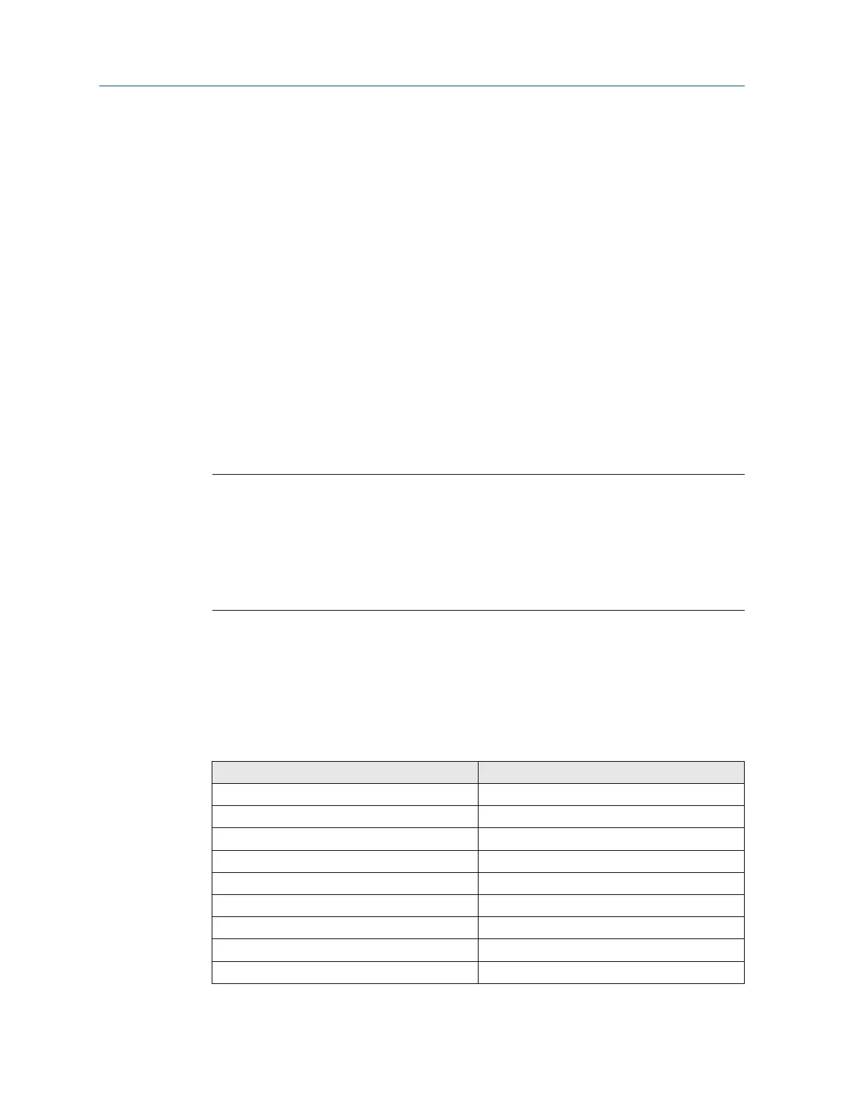
Typical power cable resistance at 68°F (20.0°C)
Wire gauge Resistance
14 AWG 0.0050 Ω/ft
16 AWG 0.0080 Ω/ft
18 AWG 0.0128 Ω/ft
20 AWG 0.0204 Ω/ft
2.5 mm
2
0.0136 Ω/m
1.5 mm
2
0.0228 Ω/m
1.0 mm
2
0.0340 Ω/m
0.75 mm
2
0.0460 Ω/m
0.50 mm
2
0.0680 Ω/m
Installation Manual Planning
00825-0100-5710 October2023
Installation Manual 9
 Loading...


