EasyManuals Logo
Home>Emerson>Transmitter>Micro Motion 5700

Emerson Micro Motion 5700 User Manual

Emerson Micro Motion 5700
58 pages
To Next Page IconTo Next Page
To Previous Page IconTo Previous Page
Page #33 background imageLoading...
Page #33 background image
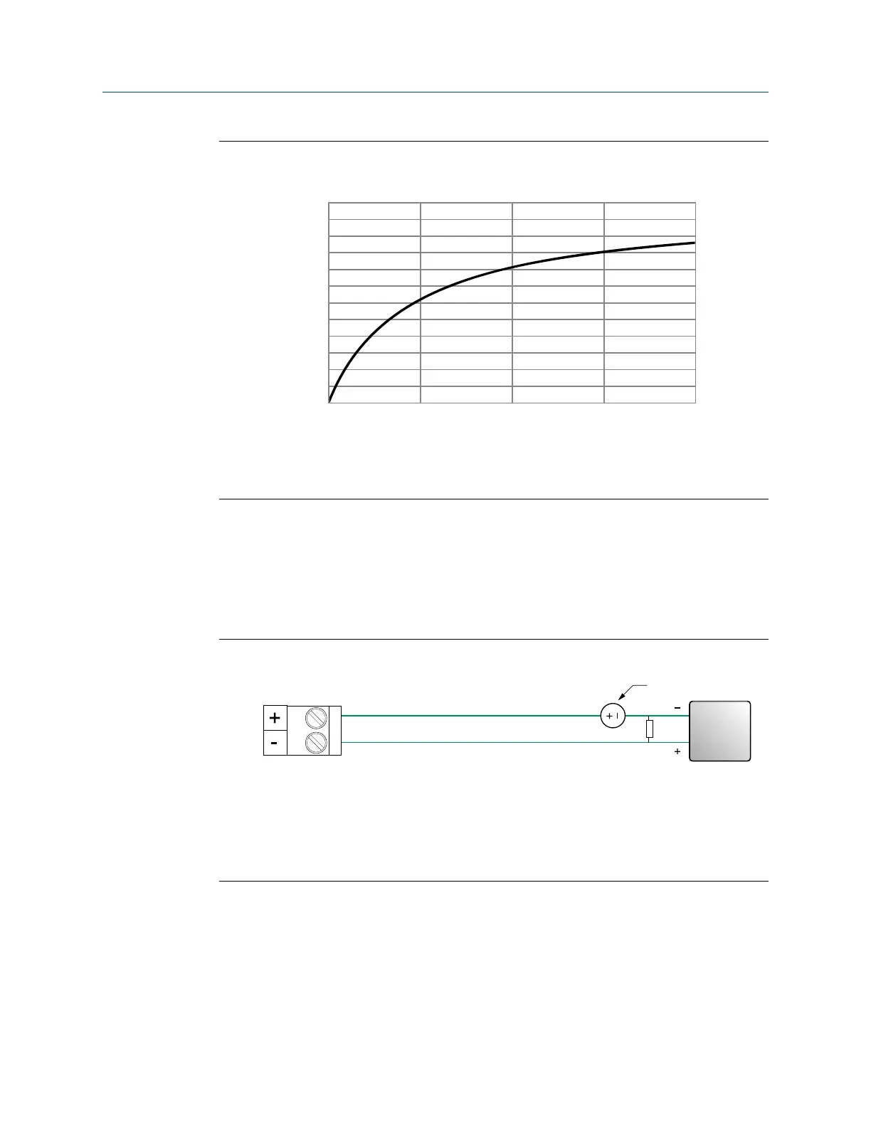
Figure 4-14: Internally powered frequency output: output amplitude versus load
resistance [24 VDC (Nom) open circuit]
0
2
4
6
8
10
12
14
16
18
20
22
24
0 2500 5000 7500 10000
A
B
A. Output amplitude (V)
B. Load resistor (Ω)
4.5.4
Wire the frequency output (externally powered Channel
D)
Procedure
Wire to the appropriate output terminal and pins.
Figure 4-15: Frequency output wiring (externally powered)
A
7
8
D
C
B
A. Frequency output
B. 3–30 VDC (maximum)
C. 500 mA current (maximum)
D. Signal device
Installation Manual Wiring the channels
MMI-20027478 April 2022
Installation Manual 33

Other manuals for Emerson Micro Motion 5700

Questions and Answers:

Question and Answer IconNeed help?

Do you have a question about the Emerson Micro Motion 5700 and is the answer not in the manual?

Emerson Micro Motion 5700 Specifications

General IconGeneral
BrandEmerson
ModelMicro Motion 5700
CategoryTransmitter
LanguageEnglish

Related product manuals