4.7 Wire the RS-485 output
Use this section to wire the RS-485 output in explosion-proof, nonincendive, or
nonhazardous installations.
Procedure
Wire to the appropriate output terminal and pins.
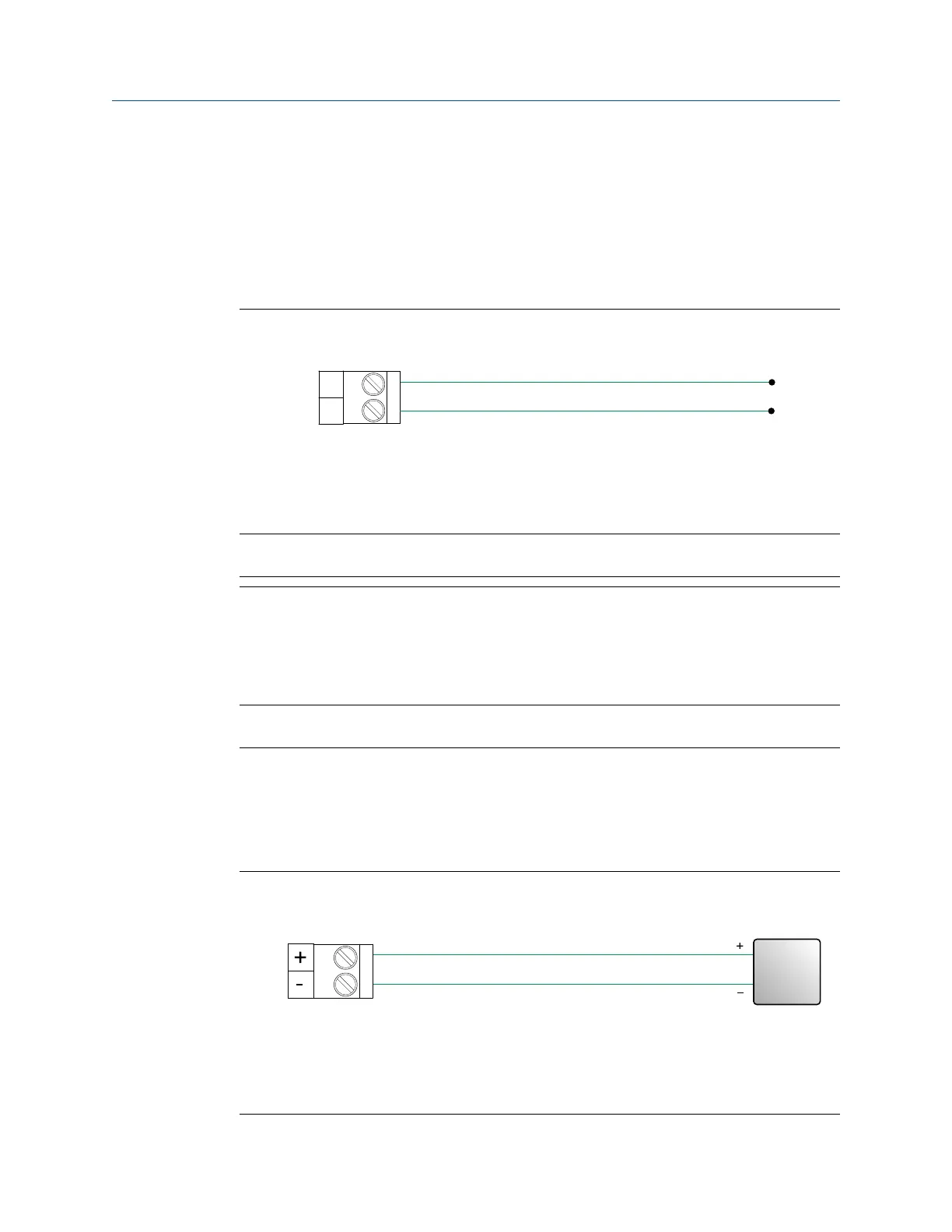
Figure 4-22: RS-485 output wiring
A. RS-485 output
B. RS-485/A
C. RS-485/B
Note
The transmitter does not provide any RS-485 termination resistance.
4.8 Wire the mA input
Use this section to wire the mA input in explosion-proof, nonincendive, or nonhazardous
installations.
Important
Meter installation and wiring should be performed only by suitably-trained personnel.
4.8.1
Wire the mA input (internally powered)
Procedure
Wire to the appropriate input terminal and pins.
Figure 4-23: mA input wiring (internally powered)
A. mA input
B. 100 Ω input resistance at Channel D
C. 4–20 mA input device
Installation Manual Wiring the channels
MMI-20027478 April 2022
Installation Manual 37

 Loading...


