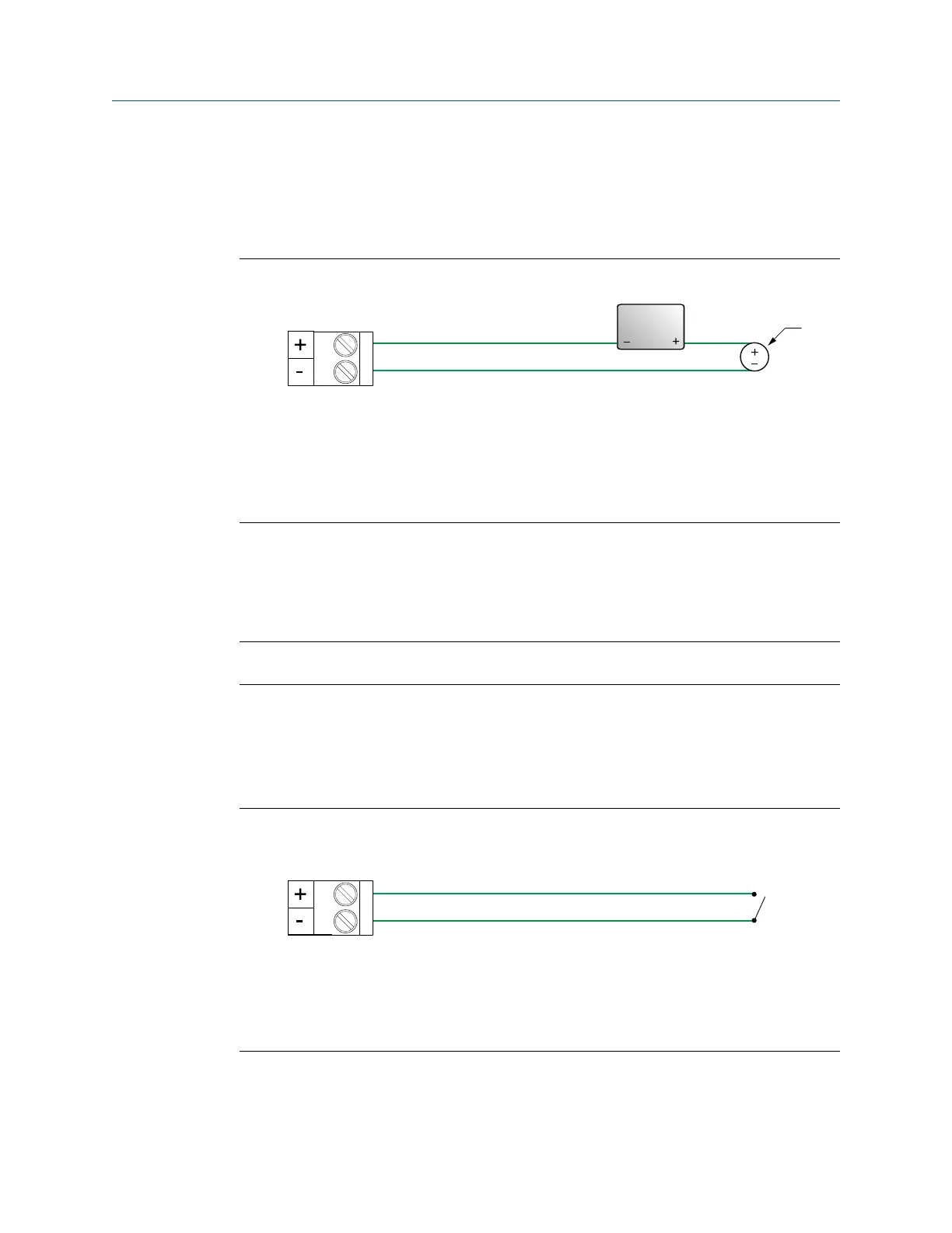
4.8.2 Wire the mA input (externally powered)
Procedure
Wire to the appropriate input terminal and pins.
Figure 4-24: mA input wiring (externally powered)
A. mA input
B. 100 Ω input resistance at Channel D
C. 4–20 mA input device
D. 30 VDC (maximum)
4.9 Wire the discrete input
Use this section to wire the discrete input in explosion-proof, nonincendive, or
nonhazardous installations.
Important
Meter installation and wiring should be performed only by suitably-trained personnel.
4.9.1
Wire the discrete input (internally powered)
Procedure
Wire to the appropriate input terminal and pins.
Figure 4-25: Discrete input wiring (internally powered)
A. Discrete input
B. Channel C or D
C. Switch
Wiring the channels Installation Manual
April 2022 MMI-20027478
38 Micro Motion 5700 Transmitters with Configurable Inputs and Outputs

 Loading...


