4.9.2 Wire the discrete input (externally powered)
Procedure
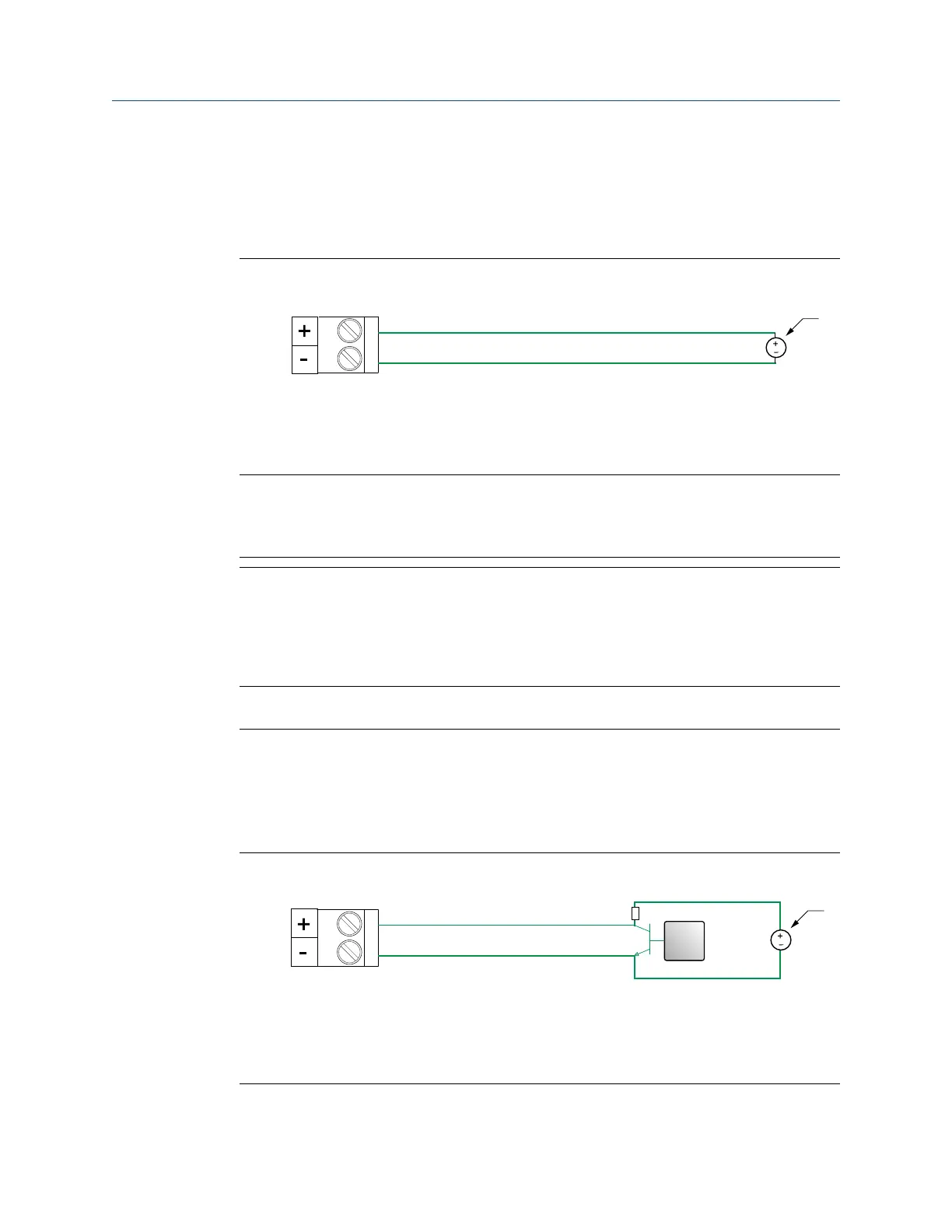
Wire to the appropriate input terminal and pins.
Figure 4-26: Discrete input wiring (externally powered)
A. Discrete input
B. Channel C or D
C. 30 VDC (maximum)
Note
• Maximum positive threshold is 3 VDC.
• Minimum negative threshold is 0.6 VDC.
4.10 Wire the frequency input
Use this section to wire the frequency input in explosion-proof, nonincendive, or
nonhazardous installations.
Important
Meter installation and wiring should be performed only by suitably-trained personnel.
4.10.1
Wire the frequency input (internally powered)
Procedure
Wire to the appropriate input terminal and pins.
Figure 4-27: Frequency input wiring (internally powered)
A. Frequency input
B. Frequency input device
C. (Optional) 1–10 KΩ resistor/open collector
D. (Optional) 3–30 VDC
Installation Manual Wiring the channels
MMI-20027478 April 2022
Installation Manual 39

 Loading...


