7. Gently press the display module back onto the connector.
8. Tighten display screws.
9. Place the display cover onto the main enclosure.
10. Turn the display cover clockwise until it is fully seated.
11. Replace the end-cap clamp by tightening the cap screw.
12. Restore power to the transmitter.
3.7 Rotate the sensor wiring junction box on a
remote-mount transmitter (optional)
In remote-mount installations, you can rotate the sensor wiring junction box on the
transmitter plus or minus 180º.
Procedure
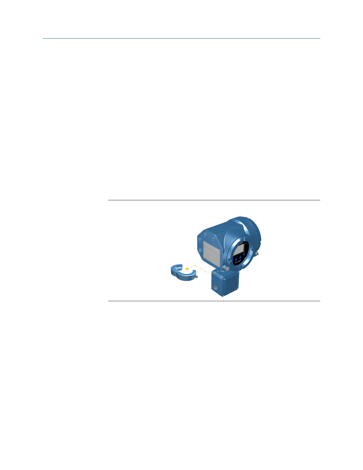
1. Using a 4 mm hex key, loosen and remove the clamp securing the sensor wiring
junction box in place.
Figure 3-16: Removal of the clamp
2. Gently rotate the junction box to the desired position.
You can rotate the junction box plus or minus 180° to any position.
Installation Manual Mounting and sensor wiring
MMI-20027478 April 2022
Installation Manual 23

 Loading...


