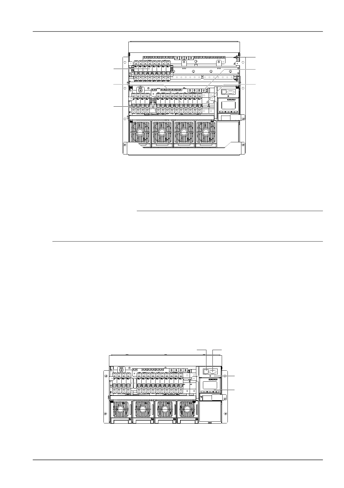
Figure 1.1 MCB and terminal positions
Connecting load cables
Connect the negative cable of the load to the upper terminal of load MCB. Connect the positive cable of the load to
the DC positive busbar. The terminals are as shown in Figure 2-5.
Connecting battery cables
1. Note
1. The batteries may have dangerous current. Before connecting the battery cables, the corresponding battery input MCBs or the
battery cell connector must be disconnected to avoid live state of the power system after installation.
2. Be careful not to reverse connect the battery. Otherwise, both the battery and the power system will be damaged!
1. Connect one end of the negative battery cable to the upper terminal of battery MCBs. Connect one end of the
positive battery cable to the DC positive bus bar.
2. Connect copper lugs to the other end of the battery cables. Bind the connecting parts with insulating tape, and put
them beside the battery. Connect the cables to the battery when the DC distribution unit is to be tested.
2.4.2 Connecting Signal Cables
S6415X2 user connector board cable connection
Take the NetSure 501 A50 power supply system as an example, the position of the user connector board is shown in
Figure 2-6. Two communication interfaces are located in the panel: Ethernet and RS232 interface. The power supply
system can be connected to Ethernet through the Ethernet interface or connected to modem through RS232
interface.
Figure 1.1 User connector board position
The interfaces of the signal transfer board are shown in Figure 2-7. The functions of the interfaces are shown in Table
2-3.
NetSure 501 A50, NetSure 501 AA0, NetSure 701 A51 19-Inch Subrack Power Supply System User Manual
 Loading...