Note
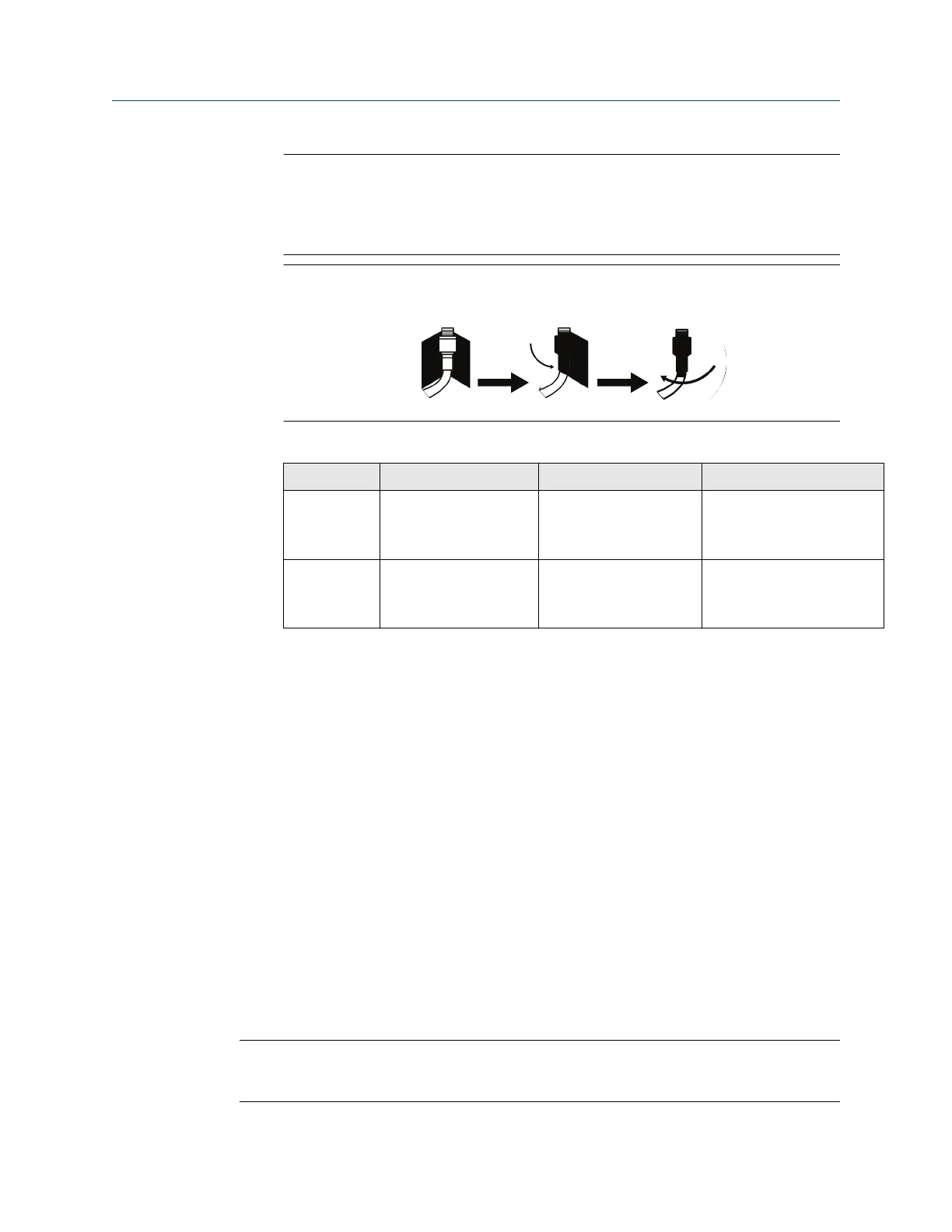
Weather proofing is required! The remote mount antenna kit includes coaxial
sealant for the cable connections for the lightning arrestor, antenna, and Gateway.
The coaxial sealant must be applied to guarantee performance of the wireless field
network. See Figure 3-4 for details on how to apply weather proofing.
Figure 3-4: Applying Coaxial Sealant to Cable Connections
Table 3-1: Remote Antenna Kit Options
Kit option Antenna Cable 1 Lightning arrestor
WL2 1/2 Wavelength Dipole
Omni-Directional +6 dB
Gain
50 ft. (15,2 m) LMR-400 Head mount, jack to plug
Gas discharge tube
0.5 dB insertion loss
WN2 1/2 Wavelength Dipole
Omni-Directional +8 dB
Gain
25 ft. (7,6 m) LMR-400 Head mount, jack to plug
Gas discharge tube
0.5 dB insertion loss
3.4 Connections
3.4.1 Grounding
The DIN rail should always be grounded in accordance with national and local electrical
codes. The most effective grounding method is a direct connection to earth ground with
minimal impedance. Grounding to the Gateway is accomplished through the DIN rail clip
on the back of the Gateway.
3.4.2
Ethernet
The Gateway is equipped with two 10/100 base-TX Ethernet communications ports (see
Figure 3-5). These connections can be used to access the Gateway’s web interface and to
communicate Modbus
®
TCP, OPC, and EtherNet/IP
™
protocols.
The primary Ethernet port (Ethernet 1) is used to connect to the host system or other
application systems. The secondary Ethernet port (Ethernet 2) can be used as a back up
connection or a maintenance port for local access to the Gateway.
Note
Unless dual Ethernet ports were specified at the time of order, the secondary Ethernet port
(Ethernet 2) will not be active.
Reference Manual
Installation
00809-0200-4410 September 2020
Emerson.com/Rosemount 21
 Loading...


