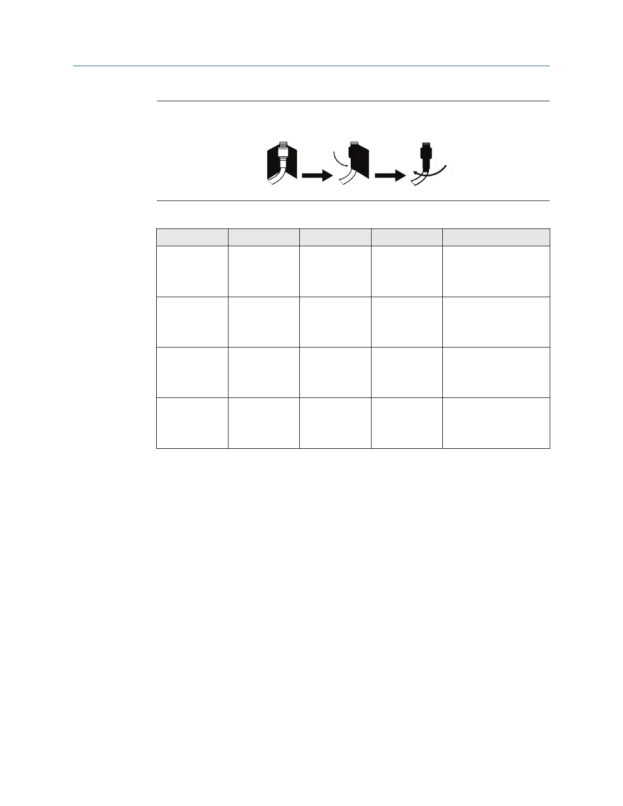
Figure 3-5: Applying Coaxial Sealant to Cable Connections
Table 3-1: Remote Antenna Kit Options
Kit option Antenna Cable 1 Cable 2 Lightning arrestor
WL2 Wavelength
Dipole Omni-
Directional +6
dB Gain
50 ft. (15,2 m)
LMR-400
N/A Head mount, jack to plug
Gas discharge tube
0.5 dB insertion loss
WL3 Wavelength
Dipole Omni-
Directional +6
dB Gain
30 ft. (9,1 m)
LMR-400
20 ft. (6,1 m)
LMR-400
In-line, jack to jack
Gas discharge tube
0.5 dB insertion loss
WL4 Wavelength
Dipole Omni-
Directional +6
dB Gain
40 ft. (12,2 m)
LMR-400
10 ft. (3,0 m)
LMR-400
In-line, jack to jack
Gas discharge tube
0.5 dB insertion loss
WN2 Wavelength
Dipole Omni-
Directional +8
dB Gain
25 ft. (7,6 m)
LMR-400
N/A Head mount, jack to plug
Gas discharge tube
0.5 dB insertion loss
3.4 Connecting
All connections to the Gateway can be made at the terminal block, which is located in the
lower junction box section of the enclosure. The terminal block label is located on the
inside of the lower cover. See Figure 3-6 for the standard terminal block label.
The junction box portion of the enclosure has four conduit entries for power and
communications wiring. Do not run communication wiring in conduit or open trays with
power wiring, or near heavy electrical equipment.
Install the included conduit plugs in any unused conduit openings. For NEMA
®
4X and IP65
requirements, use thread seal (PTFE) tape or paste on male threads to provide a watertight
seal.
3.4.1
Grounding
The Gateway enclosure case should always be grounded in accordance with national and
local electrical codes. The most effective grounding method is a direct connection to earth
ground with minimal impedance. Ground the Gateway by connecting the external
grounding lug to earth ground. The connection should be 1Ω or less. The external ground
plug is located below the Gateway enclosure and is identified by the following symbol:
Reference Manual
Installation
00809-0200-4420 September 2020
Emerson.com/Rosemount 23
 Loading...


