4
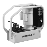
Figure 4, Wiring Diagram
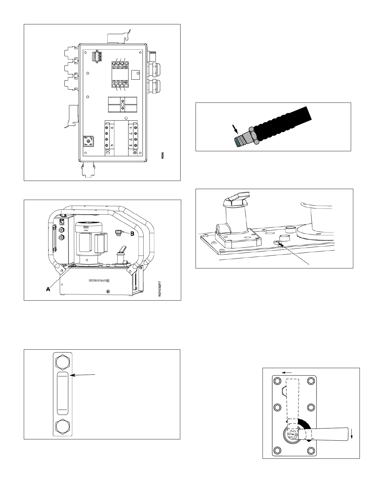
Figure 5
4.6 Fluid Level
Check the oil level of the pump prior to start-up, and add oil, if
necessary, by removing the breather cap.The reservoir is full when
the oil level reaches the top mark of the sight glass bolt. (Fig. 6).
Figure 6
IMPORTANT: Add oil only when all system components are
fully retracted, or the system will contain more oil than the
reservoir can hold.
4.7 Hydraulic Connections
Thread hose(s) into outlet port(s) of the valve. Apply 1
1
⁄2 wraps of
Teflon tape or other suitable sealant to the hydraulic hose fitting,
leaving the first complete thread free of tape or sealant as shown
in Figure 7.
For 2-way valve connect to front port.
For 3-way valve connect to port "A".
For 4-way valve connect advance to port "A:, retract to port "B".
For Dump and Dump-Hold valves connect to port "A".
Figure 7
If a remote valve is used, connect the tank line to the return-to-
tank port on top of the reservoir (see Figure 8).
Figure 8
5.0 OPERATION
1. Check the oil level of pump and add oil if necessary.
2. Make sure the shipping plug has been removed and the
breather cap is installed.
3. The control valve must be in the neutral or retract position.
4. The ON-OFF switch is located on the electrical enclosure for
most models. For GPEM models, the switch may be located
on the motor.
5.1 Valve Operation
VM-2 (See Fig. 9)
1. Advance
2. Retract
 Loading...