IQ8 Commercial Microinverter grid-tied PV system
66 © 2023 Enphase Energy Inc. All rights reserved. November 2023
USG-00026-1.0
9 Appendix B: Phase balancing in IQ8 Commercial
installations using the three-phase QD Cable phase
rotation
Enphase IQ8 Commercial Microinverters has a 4-pin output configuration (L1, L2, L3, and neutral sense)
with power on two pins and sensing on the other two pins. The single-phase IQ8 Commercial
Microinverter achieves the three-phase configuration and phase balancing using the three-phase QD
Cable phase rotation. This topic helps you understand the phase rotation configuration for QD Cable
and how phase balancing is achieved for IQ8 Commercial Microinverter System.
9.1 AC QD Cable for IQ8 Commercial Microinverter
QD Cable is a 12 AWG cable with four conductors for L1, L2, L3, and neutral sense. QD Cable has power
on two phases (P1, P2 Pins) and sensing on the other phase and neutral for phase loss sensing (P3, P4
Pins). This arrangement alternates between phases for each drop to achieve self-phase balancing. The
QD Cable 4-pin male connectors plug directly into the IQ8 Commercial Microinverters, whose double
insulated rating requires no ground conductors.
Based on PV module orientation specific to the installation site, QD Cable provides the following
ordering options.
Table 19: QD Cable types/ordering options
QD Cable types/ordering options
Model number
Max voltage
Size
Connector
spacing
PV module
Connectors
count per box
QD-12-13-120 277 VAC 12 AWG 1.3 m (4.3 ft) Portrait 120
QD-12-20-120 277 VAC 12 AWG 2.0 m (6.6 ft) Landscape 120
QD-12-25-108 277 VAC 12 AWG 2.5 m (8.2 ft) Landscape 108
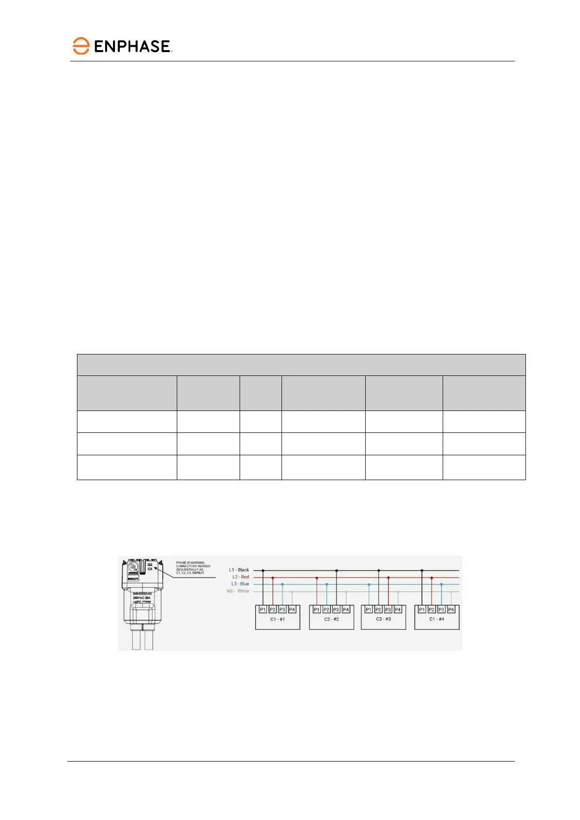
9.1.1 Phase rotation for QD Cable
Each connector on the QD Cable is marked with Phase ID C1, C2, and C3, which shows the phase
rotation across the connectors in the QD Cable as shown below, and the similar phase rotation
arrangement continues across the cable.
Figure 45: QD Cable connector and typical phase rotation arrangement
QD Cable has two different configurations for SKUs to achieve phase rotation and phase balancing and
to maintain a maximum 1% voltage rise in QD Cable.
 Loading...