Maintenance 7. Arm #3
158 G10 / G20 Rev.20
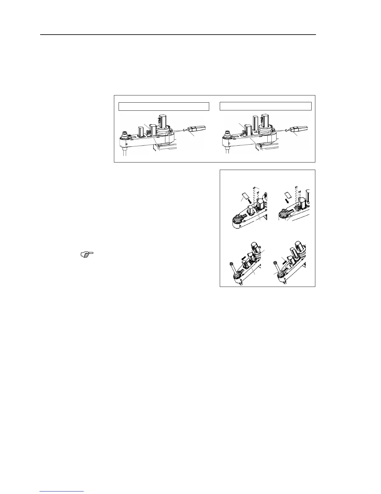
Apply the proper tension to the Z belt, and then secure the Joint #3 motor unit.
a suitable cord or string around the Joint #3 motor unit near its
. Then, pull the cord using a force gauge or similar tool to apply
the specified tension shown in the figure on the right
Make sure that the brake cables do not touch the pulley.
G10 : Z belt tension = 130 N (13.3 kgf)
G20 : Z belt tension = 130 N (13.3 kgf)
When you use the plate of 4
mounting, mount the plate.
When you use the plate of 3
mount the plate with pressing it to the motor
side*.
G10 series: Joint #4 motor side
G20 series: Joint #3 motor side
When mounting the battery unit mounting
bolts, be sure to keep the connectors
connected to the battery unit.
If connectors of the battery unity are
disconnected, you need to perform
calibration again.
Connect the connectors X231, X31, and X63.
-bundle the cables in their original positions with a wire tie removed in step (5).
allow unnecessary strain on the cables.
top cover and the arm bottom cover.
For details, refer to Maintenance: 3. Covers.
Perform the calibration of Joint #3.
For details on the calibration method, refer to Maintenance: 14. Calibration.
 Loading...


