Setup & Operation 2. Specifications
G10 / G20 Rev.20 19
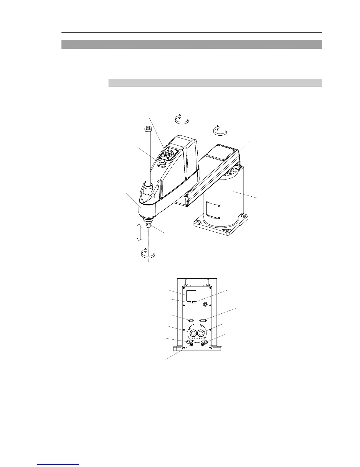
2.3 Part Names and Outer Dimensions
G10-65***, G10-85*** manipulator of S/N: 1**** or later is different from other models
in its form. For the detail, refer to Setup & Operation 2.3.4 G10-65***, G10-85***: For
S/N: 1**** or later.
2.3.1 Table Top Mounting
Standard-model : G10/G20-***S
Joint #3 and #4
brake release
switch
Signature label
(Serial No. of Manipulator)
Fitting (black or blue)*
for ø 6 mm pneumatic tube
User connector
(15-pin D-sub connector)
User connector
(9-pin D-sub connector)
Fitting (black or blue)*
for ø 4 mm pneumatic tube
Fitting (white)
for ø 6 mm pneumatic tube
Fitting (white)
for ø 4 mm pneumatic tube
* Color differs depending on the shipment time
- The brake release switch affects both Joints #3 and #4. When the brake release switch is pressed
in emergency mode, the brakes for both Joints #3 and #4 are released simultaneously.
- When the LED lamp is lighting or the controller power is on, the current is being applied to the
manipulator. Performing any work with the power ON is extremely hazardous and it may result
in electric shock and/or improper function of the robot system. Make sure to turn OFF the
controller power before the maintenance work.
 Loading...


