Operation Manual
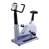
Ergometer
Type er800S
Version: 05/02 29 er800S Operation Manual
Art-Nr: 475.051
Appendix C: Service
ATTENTION: Service interventions of any type may only be carried out by ergoline
authorized personnel. Improper calibration can lead to endangerment
of the test subject. ergoline will not guarantee nor accept any
responsibility for damage to the unit or injury to persons which result
from improper service interventions.
C.1 Calibrating the Analog I/O Signals
C.1.a Calibrating the Analog Load Control Input
Calibration of the analog load control input is done with service connector A (see
next page). Insert service connector A into the jack J2 on the ergometer console.
The leftmost display will then show an undefined load value. Now connect a calibrated
voltage source with a value of between 1V and 3V to service connector A. The
displayed load value may now be adjusted to the calibrated voltage source (1.00V =
100 watt) by using the yellow „+/-“ arrow keys.
Service connector A can be removed when the displayed value remains stable at the
desired value. This completes load input calibration.
C.1.b Calibrating the Analog Load Output
Calibration of the analog load output is done with service connector B (see next
page). Insert service connector B into the jack J2 on the ergometer console. The
test conductors of service connector B now have a voltage that corresponds to a
load value of 250 watt. This voltage can now be adjusted by using the yellow „+/-“
arrow keys. Set the voltage in accordance with the ECG manufacturer’s instructions
(e.g. 2.50V = 250 watt).
The maximum output voltage is 3.5V.
Service connector B can be removed when the voltage at the output remains stable
at the desired level. This completes calibration of the analog load output.

 Loading...