EasyManua.ls Logo

ESAB Cutmaster 60 User Manual

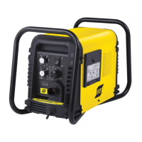
ESAB Cutmaster 60
68 pages
To Next Page IconTo Next Page
To Previous Page IconTo Previous Page
Page #9 background imageLoading...
Page #9 background image
ESAB CUTMASTER 60
Manual 0-5402 INTRODUCTION
2-1
SECTION 2 SYSTEM:
INTRODUCTION
2.01 How To Use This Manual
This Owner’s Manual applies to just specification or
part numbers listed on page i.
To ensure safe operation, read the entire manual,
including the chapter on safety instructions and
warnings.
Throughout this manual, the words WARNING, CAU-
TION, and NOTE may appear. Pay particular attention
to the information provided under these headings.
These special annotations are easily recognized as
follows:
NOTE!
An operation, procedure, or background informa-
tion which requires additional emphasis or is help-
ful in ecient operation of the system.
!
CAUTION
A procedure which, if not properly followed, may
cause damage to the equipment.
!
WARNING
A procedure which, if not properly followed, may
cause injury to the operator or others in the operat-
ing area.
WARNING
Gives information regarding possible electrical
shock injury. Warnings will be enclosed in a box
such as this.
Additional copies of this manual may be purchased
by contacting ESAB at the address and phone num-
ber in your area listed on back cover of this manual.
Include the Owner’s Manual number and equipment
identification numbers.
Electronic copies of this manual can also be down-
loaded at no charge in Acrobat PDF format by going
to the ESAB web site listed below
http://www.esab.com.cn
2.02 Equipment Identification
The unit’s identification number (specification or part
number), model, and serial number usually appear
on a data tag attached to the rear panel. Equipment
which does not have a data tag such as torch and
cable assemblies are identified only by the specifica-
tion or part number printed on loosely attached card
or the shipping container. Record these numbers on
the bottom of page i for future reference.
2.03 Receipt Of Equipment
When you receive the equipment, check it against the
invoice to make sure it is complete and inspect the
equipment for possible damage due to shipping. If
there is any damage, notify the carrier immediately to
file a claim. Furnish complete information concerning
damage claims or shipping errors to the location in
your area listed in the inside back cover of this manual.
Include all equipment identification numbers as
described above along with a full description of the
parts in error.
Move the equipment to the installation site before
un-crating the unit. Use care to avoid damaging the
equipment when using bars, hammers, etc., to un-
crate the unit.

Table of Contents

Questions and Answers:

ESAB Cutmaster 60 Specifications

General IconGeneral
BrandESAB
ModelCutmaster 60
CategoryWelding System
LanguageEnglish

Summary

SECTION 1: SAFETY

1.0 Safety Precautions

General safety guidelines and recommendations for operating the equipment.

SECTION 2 SYSTEM: INTRODUCTION

2.01 How To Use This Manual

Instructions on how to navigate and use the manual effectively.

2.02 Equipment Identification

Details on identifying the unit's model, serial number, and part numbers.

2.03 Receipt Of Equipment

Procedures for checking received equipment for completeness and damage.

2.04 Power Supply Specifications

2.05 Input Wiring Specifications

2.06 Power Supply Features

SECTION 2 TORCH: INTRODUCTION

2T.01 Scope of Manual

Details the manual's coverage of SL60/Manual and SL100/Mechanized Plasma Cutting Torches.

2T.02 General Description

Explains the basic design and function of plasma torches and gas flow.

2T.03 Specifications

Provides technical specifications for torch configurations, leads, and parts.

2T.04 Options And Accessories

2T.05 Introduction to Plasma

SECTION 3 SYSTEM: INSTALLATION

3.01 Unpacking

Instructions for identifying and inspecting equipment after receiving it.

3.02 Lifting Options

Details on safe lifting procedures and options for the power supply unit.

3.03 Primary Input Power Connections

Guidance on connecting the primary input power, including voltage and wiring requirements.

3.04 Gas Connections

Installing Optional Two - Stage Air Filter Kit

Using High Pressure Air Cylinders

SECTION 3 TORCH: INSTALLATION

3T.01 Torch Connections

Procedure for connecting the torch to the power supply unit.

3T.02 Setting Up Mechanical Torch

Instructions for mounting and aligning the mechanical torch for cutting.

SECTION 4 SYSTEM: OPERATION

4.01 Front Panel Controls / Features

Description of the power supply's front panel controls and indicators for operation.

4.02 Preparations for Operation

SECTION 4 TORCH: OPERATION

4T.01 Torch Parts Selection

Guidance on selecting appropriate torch parts for different cutting operations.

4T.02 Cut Quality

Factors influencing cut quality and characteristics of a good cut.

4T.03 General Cutting Information

4T.04 Hand Torch Operation

Shield Cup With Straight Edge

Drag Cutting With a Hand Torch

Piercing With Hand Torch

4T.05 Gouging

4T.06 Mechanized Torch Operation

4T.07 Parts Selection for Manual and Mechanized Torch Cutting

4T.08 Recommended Cutting Speeds for Mechanized Torch With Exposed Tip

4T.09 Recommended Cutting Speeds for Mechanized Torch With Shielded Tip

PATENT INFORMATION

Plasma Cutting Torch Patents

Lists US and Foreign patents covering plasma cutting torch parts.

SECTION 5 SYSTEM: SERVICE

5.01 General Maintenance

Routine maintenance tasks for the power supply unit, categorized by frequency.

5.02 Maintenance Schedule

5.03 Common Faults

5.04 Fault Indicator

5.05 Basic Troubleshooting Guide

5.06 Power Supply Basic Parts Replacement

Optional Single-Stage Filter Element Replacement

Optional Two-Stage Filter Element Replacement

SECTION 5 TORCH: SERVICE

5T.01 General Maintenance

Procedures for cleaning and lubricating torch components for optimal performance.

5T.02 Inspection and Replacement of Consumable Torch Parts

SECTION 6: PARTS LISTS

6.01 Introduction

Overview of the parts list breakdown and arrangement.

6.02 Ordering Information

Guidelines for ordering replacement parts, including necessary information.

6.03 Power Supply Replacement

Details on what is included with a replacement power supply unit.

6.04 Replacement Power Supply Parts

6.05 Options and Accessories

6.06 Replacement Parts for Hand Torch

6.07 Replacement Parts - for Machine Torches with Unshielded Leads

6.08 Replacement Shielded Machine Torch Leads Assemblies

6.09 Torch Consumable Parts (SL60)

6.10 Torch Consumable Parts (SL100)

APPENDIX 1: SEQUENCE OF OPERATION (BLOCK DIAGRAM)

APPENDIX 2: DATA TAG INFORMATION

APPENDIX 3: TORCH PIN - OUT DIAGRAMS

APPENDIX 4: TORCH CONNECTION DIAGRAMS

APPENDIX 5: SYSTEM SCHEMATIC, 380/400V UNITS

APPENDIX 6: Publication History

Related product manuals