Instruction Manual
D103175X012
GX Valve and Actuator
July 2017
7
Actuator Disassembly (For Air‐to‐Close Constructions ‐ see figure 20 or 21)
1. Remove the stem connector nut half (key 23), stem connector bolt half (key 24), and travel indicator (key 26).
WARNING
To avoid personal injury or property damage due to actuator springs (key 12) being under compression, remove the long
cap screws (key 16) last.
The upper actuator casing may remain fixed to the diaphragm and lower casing during disassembly, even if the casing cap
screws have been loosened. If this happens, the actuator springs are still under compression. The upper casing could
suddenly come loose and jump, due to the compressed energy of the springs. If the upper casing is stuck to the diaphragm
and lower casing when you begin loosening the casing cap screws, pry the casings apart with a prying tool. Always ensure
that the springs are dispersing energy and the upper casing is moving against the long bolts during disassembly.
2. Remove the short actuator casing cap screws and hex nuts (keys 17 and 18) first. Once these have been removed
from the actuator assembly, carefully remove the long actuator cap screws and hex nuts (keys 16 and 18),
alternating between them to gradually release the spring energy (compression).
3. Remove the upper diaphragm casing (key 9).
4. Lift off the actuator stem/diaphragm assembly (includes keys 22, 11, 10, 14, 13, 109, and 15) and remove the cap
screw (key 14), actuator spacer (key 13), actuator rod (key 22), and washer (key 15).
5. Remove the actuator springs (key 12 and/or 82).
6. Replace the diaphragm (key 10), diaphragm O-ring (key 109), actuator rod bushing (key 19), and actuator rod seal
(key 20), as needed.
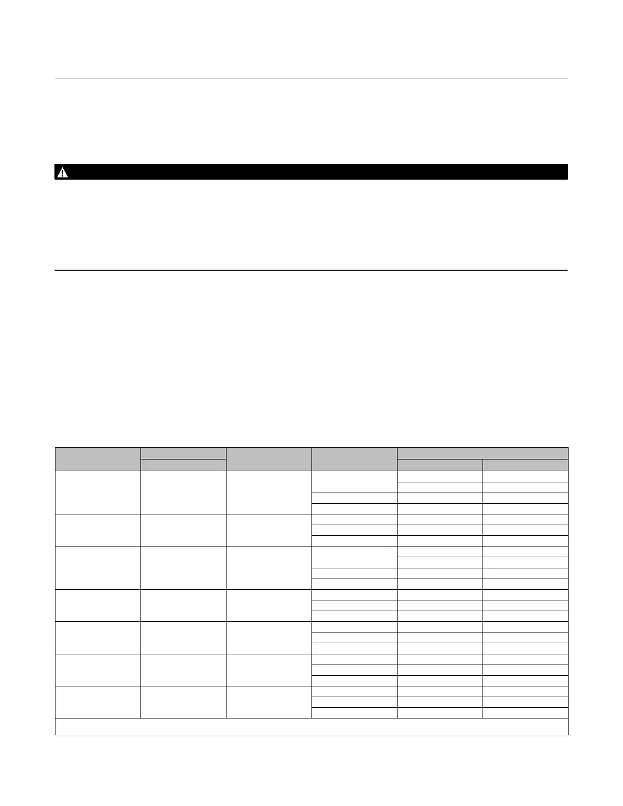
Table 2. Actuator Spring Configuration Based on Minimum Supply Pressure
(1)
ACTUATOR SIZE
TRAVEL
STEM MATERIAL
MINIMUM SUPPLY
PRESSURE
SPRING CONFIGURATION
mm Air‐to‐Open Air‐to‐Close
225 20
S20910, N05500
S31603
4 bar (58 psi)
A6 A3
A4
(2)
A4
(2)
3 bar (44 psi) A4 A3
2 bar (29 psi) A3 A2
225 20
S31803, N10675,
N06022
4 bar (58 psi) A6 A3
3 bar (44 psi) A4 A3
2 bar (29 psi) A3 A2
750 20
S20910, N05500
S31603
4 bar (58 psi)
B6 B4
B6
(2)
B6
(2)
3 bar (44 psi) B6 B4
2 bar (29 psi) B4 B4
750 20
S31803, N10675,
N06022
4 bar (58 psi) B4 B4
3 bar (44 psi) B4 B4
2 bar (29 psi) B4 B4
750 40
S20910, N05500
S31603
4 bar (58 psi) C12 C6
3 bar (44 psi) C8 C3
2 bar (29 psi) C4 C3
750 40
S31803, N10675,
N06022
4 bar (58 psi) C8 C6
3 bar (44 psi) C8 C3
2 bar (29 psi) C4 C3
1200 40 or 60
S20910, N05500
S31603
4 bar (58 psi) D15 D15
3 bar (44 psi) D15 D15
2 bar (29 psi) N/A N/A
1. Only applicable to actuators with spring information on the nameplate (see figure 2).
2. Only applicable to Cavitrol III constructions.

 Loading...