Instruction Manual
D103175X012
GX Valve and Actuator
July 2017
8
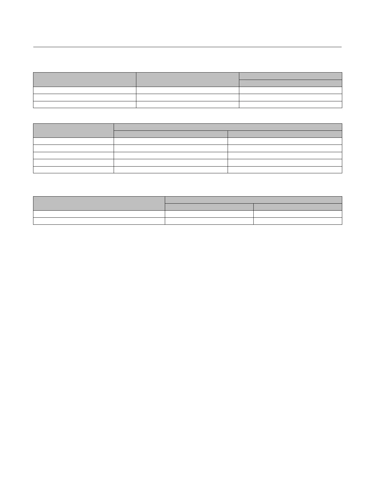
Table 3. Fisher GX Maximum Rated Travel
ACTUATOR SIZE NUMBER OF CASING BOLTS
TRAVEL
mm
225 6 20
750 10 20 or 40
1200 16 40 or 60
Table 4. Body Nut (Key 7) Torque Requirements
VALVE SIZE
TORQUE
NSm lbfSft
DN15, 20, 25 (NPS 1/2, 3/4, 1) 45.5 33.5
DN40 (NPS 1‐1/2) 79.8 58.9
DN50 (NPS 2) 79.8 58.9
DN80 (NPS 3) 163 120
DN100 and DN150 (NPS 4 and 6) 282 208
Table 5. Yoke/Extension Bonnet Nut (Key 46) Torque Requirements (used on Extension Bonnet and Bellows Bonnet
constructions)
VALVE SIZE
TORQUE
NSm lbfSft
DN15, 20, 25, 40, and 50 (NPS 1/2, 3/4, 1, 1‐1/2, and 2) 79.8 58.9
DN80 and DN100 (NPS 3 and 4) 163 120
Actuator Assembly For Air‐to‐Open Constructions (or to Change Action to Air‐to‐Open ‐ see
figure 18 or 19)
1. Install the diaphragm (key 10) on the diaphragm plate (key 11). Insert the cap screw (key 14) through the actuator
spacer (key 13) and place this assembly through the diaphragm/diaphragm plate assembly.
2. Place the diaphragm O-ring (key 109) and the washer (key 15) over the center hole of the diaphragm, so that the
convex part of the washer is facing down toward the diaphragm and contains the O-ring. Ensure the convex part of
the washer is guided in the diaphragm center hole as shown in figure 18 or 19.
3. Screw the actuator rod (key 22) onto the cap screw (key 14) and torque to 80 NSm (59.1 lbfSft). Install the actuator
stem/diaphragm assembly back into the actuator yoke (key 8).
4. Place the actuator springs (key 12 and/or 82) onto the spring locators in the diaphragm plate (key 11). See figure 3
and table 2 for proper spring quantity and arrangement.
D If the nameplate does not contain spring information, use the same quantity and arrangement as originally
installed.
5. Install the upper diaphragm casing (key 9) so that the ribs on the top of the upper diaphragm casing are
perpendicular with the yoke legs.
D For size 225 and 750 actuators, install the 2 long cap screws (key 16) and hex nuts (key 18) 180 degrees apart from
each other and in line with the actuator yoke legs.
D For size 1200 actuators, install the 4 long cap screws (key 16) and hex nuts (key 18) 90 degrees from each other,
with two of them in line with the actuator yoke legs.
6. Tighten the long cap screws (key 16) and hex nuts (key 18), alternating between them to gradually compress the
springs, until the two casing halves and diaphragm touch.
7. Install the remaining short cap screws (key 17) and hex nuts (key 18) to the casing.
8. Tighten the actuator casing cap screws evenly using a cross‐tightening procedure. Torque to 55 NSm (40 lbfSft).

 Loading...