Instruction Manual
D103175X012
GX Valve and Actuator
July 2017
9
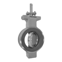
9. If you had previously removed the actuator assembly from the valve, place the actuator assembly back onto the
valve body (key 1). Install the four body nuts (key 7), but tighten them only finger‐tight.
10. Connect a separate air supply to the actuator air supply connection (as shown on the yoke in figure 18 or 19) and
apply sufficient air pressure to raise the actuator rod (key 22) to the travel stop.
Note
If converting from air‐to‐close to air‐to‐open action, first move the vent cap (key 21) from the air supply connection on the yoke
leg (see figure 20 or 21) to the top of the casing (see figure 18 or 19).
11. For standard bonnet constructions (figures 18, 19, 20, and 21), tighten the body nuts (key 7) evenly using a
cross‐tightening procedure. See table 4 for torque requirements.
For extension and bellows bonnet constructions (figures 22 and 23), tighten the bonnet nuts (key 46) evenly using a
cross‐tightening procedure. See table 5 for torque requirements.
12. With the valve plug/stem (key 3) on the seat, thread the stem adjustor nut (key 27) up until it is the rated travel
distance specified in table 3 from the actuator rod (key 22). Thread the locknut (key 28) up against the stem locknut
and tighten per table 6.
Table 6. Stem Connector Torque Values
PART STEM MATERIAL
TORQUE
NSm LbfSft
M8 Stem Connector Cap Screws All 35 26
M10 Stem Connector Jam Nut
(Rie 4606 Coated)
S31603, S20910, N05500 48 35
N06022, S31803, N10675 35 26
M14 Stem Connector Jam Nut
S31603, S20910, N05500 175 129
N06022, S31803, N10675 138 102
13. Stroke the actuator rod until it contacts the stem adjuster nut (key 27) and install the stem connector halves and
travel indicator (keys 23, 24, and 26) with the cap screws (key 25). Install the stem connector halves in the proper
orientation so that when looking at the inside of the stem connector halves, the flats are down and the beveled
surfaces are up.
14. Align the pointer of the travel indicator (key 26) with the appropriate mark on the travel scale.
15. Tighten the stem connector cap screws (key 25) to 35 NSm (26 lbfSft).
16. Release the actuator pressure.
Note
For air‐to‐open action, the air supply tubing must be connected to the actuator yoke at the air supply connection, see figure 18 or
19. (If converting from air‐to‐close to air‐to‐open, the tubing will need to be re‐routed to this location).
Actuator Assembly For Air‐to‐Close Constructions (or to Change Action to Air‐to‐Close ‐ see
figure 20 or 21)
1. Position the upper diaphragm casing (key 9) upside down on the bench so that it lays flat and not off balance.
Note
If converting from air‐to‐open to air‐to‐close action, first move the vent cap (key 21) from the top of the casing (see figure 18 or
19) and thread into the air supply connection on the yoke leg (see figure 20 or 21).

 Loading...