The measurement formula
22
2. Reflected emission from ambient sources = (1 – ε)τW
refl
, where (1 – ε) is the reflec-
tance of the object. The ambient sources have the temperature T
refl
.
It has here been assumed that the temperature T
refl
is the same for all emitting surfa-
ces within the halfsphere seen from a point on the object surface. This is of course
sometimes a simplification of the true situation. It is, however, a necessary simplifica-
tion in order to derive a workable formula, and T
refl
can – at least theoretically – be giv-
en a value that represents an efficient temperature of a complex surrounding.
Note also that we have assumed that the emittance for the surroundings = 1. This is
correct in accordance with Kirchhoff’s law: All radiation impinging on the surrounding
surfaces will eventually be absorbed by the same surfaces. Thus the emittance = 1.
(Note though that the latest discussion requires the complete sphere around the ob-
ject to be considered.)
3. Emission from the atmosphere = (1 – τ)τW
atm
, where (1 – τ) is the emittance of the at-
mosphere. The temperature of the atmosphere is T
atm
.
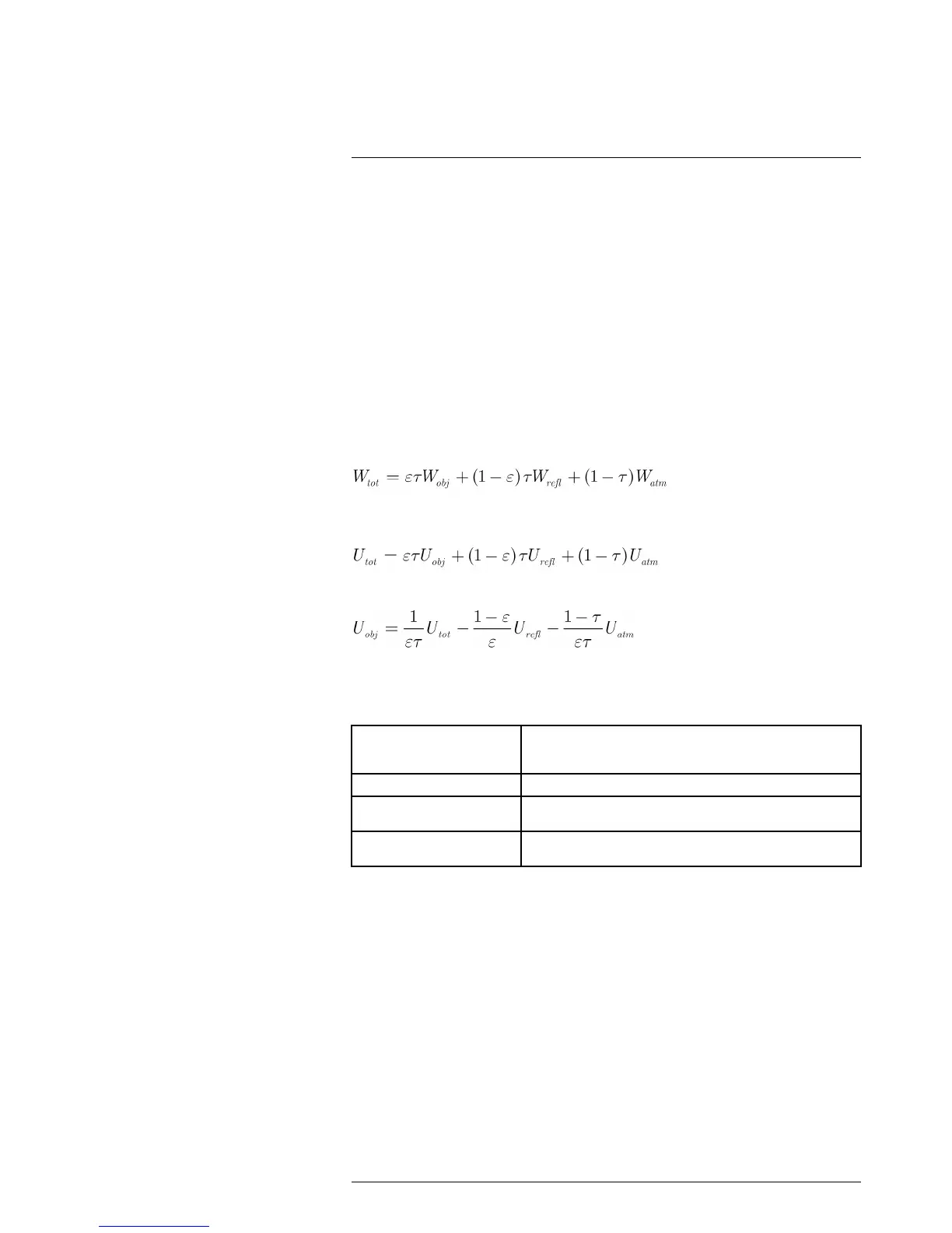
The total received radiation power can now be written (Equation 2):
We multiply each term by the constant C of Equation 1 and replace the CW products by
the corresponding U according to the same equation, and get (Equation 3):
Solve Equation 3 for U
This is the general measurement formula used in all the FLIR Systems thermographic
equipment. The voltages of the formula are:
Table 22.1 Voltages
U
obj
Calculated camera output voltage for a blackbody of temperature
T
obj
i.e. a voltage that can be directly converted into true requested
object temperature.
U
tot
Measured camera output voltage for the actual case.
U
refl
Theoretical camera output voltage for a blackbody of temperature
T
refl
according to the calibration.
U
atm
Theoretical camera output voltage for a blackbody of temperature
T
atm
according to the calibration.
The operator has to supply a number of parameter values for the calculation:
• the object emittance ε,
• the relative humidity,
• T
atm
• object distance (D
obj
)
• the (effective) temperature of the object surroundings, or the reflected ambient tem-
perature T
refl
, and
• the temperature of the atmosphere T
atm
This task could sometimes be a heavy burden for the operator since there are normally
no easy ways to find accurate values of emittance and atmospheric transmittance for the
actual case. The two temperatures are normally less of a problem provided the surround-
ings do not contain large and intense radiation sources.
A natural question in this connection is: How important is it to know the right values of
these parameters? It could though be of interest to get a feeling for this problem already
here by looking into some different measurement cases and compare the relative
#T559498; r.22370/22370; en-US
96
 Loading...