The measurement formula
22
magnitudes of the three radiation terms. This will give indications about when it is impor-
tant to use correct values of which parameters.
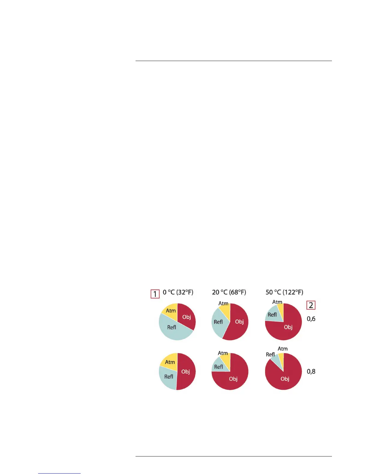
The figures below illustrates the relative magnitudes of the three radiation contributions
for three different object temperatures, two emittances, and two spectral ranges: SW and
LW. Remaining parameters have the following fixed values:
• τ = 0.88
• T
refl
= +20°C (+68°F)
• T
atm
= +20°C (+68°F)
It is obvious that measurement of low object temperatures are more critical than measur-
ing high temperatures since the ‘disturbing’ radiation sources are relatively much stron-
ger in the first case. Should also the object emittance be low, the situation would be still
more difficult.
We have finally to answer a question about the importance of being allowed to use the
calibration curve above the highest calibration point, what we call extrapolation. Imagine
that we in a certain case measure U
tot
= 4.5 volts. The highest calibration point for the
camera was in the order of 4.1 volts, a value unknown to the operator. Thus, even if the
object happened to be a blackbody, i.e. U
obj
= U
tot
, we are actually performing extrapola-
tion of the calibration curve when converting 4.5 volts into temperature.
Let us now assume that the object is not black, it has an emittance of 0.75, and the trans-
mittance is 0.92. We also assume that the two second terms of Equation 4 amount to 0.5
volts together. Computation of U
obj
by means of Equation 4 then results in U
obj
= 4.5 /
0.75 / 0.92 – 0.5 = 6.0. This is a rather extreme extrapolation, particularly when consider-
ing that the video amplifier might limit the output to 5 volts! Note, though, that the applica-
tion of the calibration curve is a theoretical procedure where no electronic or other
limitations exist. We trust that if there had been no signal limitations in the camera, and if
it had been calibrated far beyond 5 volts, the resulting curve would have been very much
the same as our real curve extrapolated beyond 4.1 volts, provided the calibration algo-
rithm is based on radiation physics, like the FLIR Systems algorithm. Of course there
must be a limit to such extrapolations.
 Loading...