2-7
2.2.5 Terminal functions and wiring order
Main circuit terminals and grounding terminals
The table below shows the order of wiring and terminal functions. Carry out wiring in the order shown in Table
2.4 below.
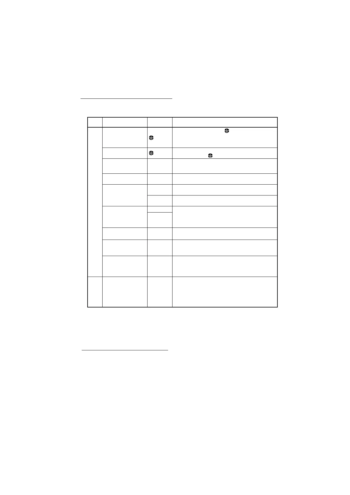
Table 2.4 Order of Wiring and Functions of Main Circuit Terminals
Primary grounding
terminals for inverter
enclosure
The two grounding terminals ( G) can be either used for
the power supply wiring (primary circuit) or motor wiring
(secondary circuit). Be sure to ground either of the two
grounding terminals for safety and noise reduction.
Secondary grounding
terminals for motor
Connect the secondary grounding wire for the motor to the
grounding terminal (
G).
Inverter output
terminals
Connect the three wires of the 3-phase motor to terminals
U, V, and W, taking care of the correct motor phase
correspondence. (*1)
Inverter output for Short
circuit
For a short circuit for PMS motor.
These outputs are connected internally to U, V, W.
Auxiliary control power
input terminals *1
Connect the power as for the 24VDC to these terminals as
a control circuit power backup.
Connect the same AC power as for the main circuit to these
terminals as a control circuit power backup.
DC reactor connection
terminals *2
Connect a DC reactor (DCR) to improve the power factor
and to fulfill with EN 12015 and EN 61000-3-12 regarding
harmonic distortion
When not connecting DCR, short-circuit by a wire.
Braking resistor
connection terminals
Connect a braking resistor to use the regeneration brake.
A DC link bus is connectable to these terminals.
When you need to use the DC link bus terminals P(+) and
N(-), consult your Fuji Electric representative.
Main circuit power input
terminals
L1/R, L2/S,
L3/T
or L1/L, L2/N
The three-phase input power lines or single-phase input
power lines are connected to these terminals.
If the power wires are connected to other terminals, the
inverter will be damaged when the power is turned ON.
Control circuit terminals
Route the wiring of the control circuit as far from that of the
main circuit as possible. Otherwise, electric noise may
cause malfunctions.
When the Enable function is not to be used, short-circuit
terminals [EN1] and [PLC] and terminals [EN2] and [PLC]
using jumper wires.
(Note) Do not connect wiring to unassigned main circuit terminals (marked with NC). For details about the
terminal block, refer to Section 2.2.3 "Terminal arrangement diagrams and screw specifications."
*1) 24V+,24V-: 200 V class series inverters and 400 V ones of FRN0032 or less
R0T0 : 400 V ones of FRN0039 or above
*2) P2,P3 : 200 V class series inverters and 400 V ones of FRN0032 or less
P1,P(+) : 400 V ones of FRN0039 or above
Wiring of Auxiliary control power input terminals
Auxiliary control power input terminals 24V+ and 24V-
Terminal rating: 22 to 32VDC, Maximum current 2.0A, Maximum power 40W.
Auxiliary control power input terminals R0 and T0
Terminal rating: 220 to 480Vac 50Hz/60Hz, Maximum current 1.0A, Maximum power 50W.
! Wiring notes
To make the machinery or equipment compliant with the EMC standards, wire the motor and inverter in
accordance with the following.
(*1) Use shielded wires for the motor cable and route the cable as short as possible. Firmly clamp the shield to the
grounded metal plate.
#
For details about wiring, refer to Chapter 8, Section 8.4 "Compliance with EMC Standards."

 Loading...


