4-2
4.3 Configuring the Function Code Data Before Test Run
Configure the function codes listed below according to the motor ratings and your machinery design values. For
the motor ratings, check the ratings printed on the motor's nameplate. For your machinery design values, ask
system designers about them.
!
To set up function code, you need to use the keypad (option) or to access their data via communications
link. For details, refer to the FRENIC-Lift LM2A series Reference Manual.
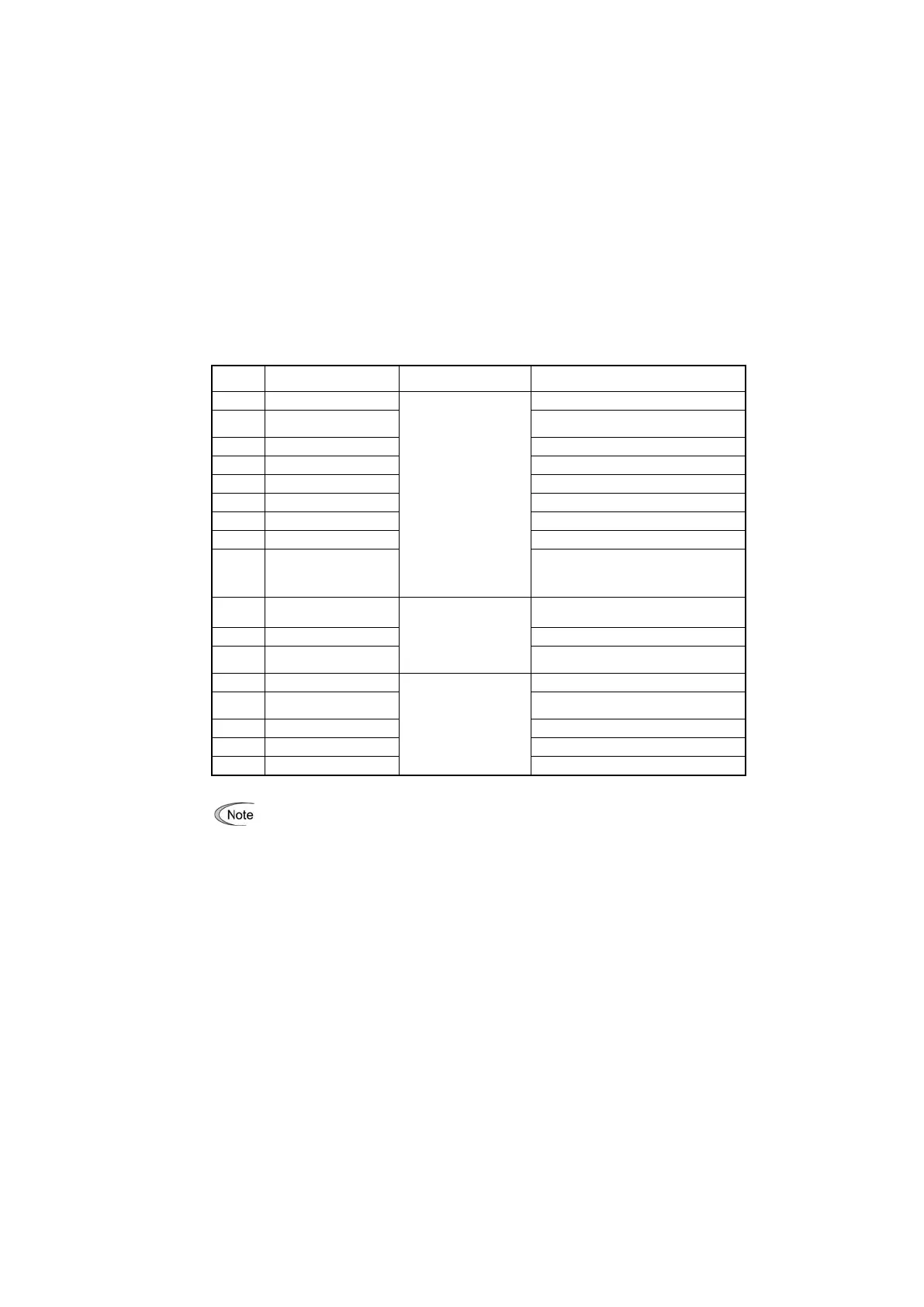
Table 4.1 Configuring Function Code Data
Motor ratings
(printed on the nameplate
of the motor)
Rated Voltage at Base
Speed
Nominal applied motor capacity.
Rated current of nominal applied motor.
No load current of the standard motor.
Primary resistance of the standard motor.
Leakage reactance of the standard motor.
0.00 (Hz)
*1
*1 The rated slip of the standard motor is
applied.
Pulse Encoder (Selection)
Depending on data sheet
of the pulse encoder.
0 : 12V/15V complementary, open collector
output circuit or 5V line driver.
Pulse Encoder (Resolution)
Magnetic pole position
Offset (Offset angle)
Motor Control Mode
Selection 1
0 : Vector control with PG
(Asynchronous motor)
0 : r/min (Speed data format)
Elevator Parameter (Speed)
1 : Motor rotates in CW(Clockwise) direction
*
Recommend to start the setting by the following order C21, P01, F03 and L31, etc.
・In any of the following cases, motor auto-tuning (P04) is necessary because the standard settings of
motor parameters for Fuji motors are not applicable:
- The motor to be driven is not a Fuji product or is a non-standard product.
- The cabling between the motor and the inverter is long.
- A reactor is inserted between the motor and inverter.
・To drive a synchronous motor, you need to tune the inverter for the offset angle of magnet pole before
running the motor. (L03)
・To drive a motor with encoder, an option card should be used which has to be ordered separately.
!
For details of motor tuning procedure refer to the FRENIC-Lift LM2A series Reference Manual.

 Loading...


